Flachantenne für stationäre Anwendung BAS 62 (216197) 1. Verwendungszweck Die Flachantenne BAS 62 ist ausschließlich für den Empfang von Satellitensignalen sowohl im analogen als auch im digitalen Frequenzbereich und nur für den Einsatz als Haushaltsantenne vorgesehen. BAS 62 erfüllt die Anforderungen entsprechend EN 50083-1; Für die Verwendung der Flachantenne BAS 62 ist diese Norm generell maßgebend.
Typ BAS 62 Einsatzbereich Stationäre Anwendung Empfangsbereich GHz 10,70-12,75 LNB-Rauschmaß dB Typ. 0,8 Verstärkung dB > 50 ° < 3 (bei Bandmitte) Halbwertsbreite LNB 1 Ausgang schaltbar, H/V, high/low Umschaltung Low-Band High-Band kHz kHz 0 22 Ausgangsfrequenz MHz 950-1950/1100-2150 Oszillatorfrequenz GHz 9,75/10,6 Güte (G/T) 11,3/12,5 GHz dB/K 13,3/13,7 V Vertikal: 11,5-14,0 - Horizontal: 16,0-19,0 Max. Stromaufnahme mA 160 Windfläche m Max.
6. Montageort Vorsicht! • Auf keinen Fall dürfen Sie Antennen unter Freileitungen montieren. Dabei könnten erforderliche Mindestabstände unterschritten werden. Halten Sie an den Seiten mindestens 1 m Abstand zu allen anderen elektrischen Einrichtungen! Es besteht Lebensgefahr, falls Sie oder Antennenteile mit elektrischen Einrichtung in Berührung kommen! • Auf keinen Fall dürfen Sie Antennen auf Gebäuden mit leicht entzündbaren Dachabdeckungen (Stroh, Reet o.ä. Materialien) montieren.
a) Anforderungen an den Antennenträger • Verwenden Sie nur Masten oder Halterungen, die speziell als Antennenträger geeignet sind. Andere Befestigungen besitzen oft nicht die erforderliche Festigkeit bei Wind- und Wettereinflüssen. • Wählen Sie einen Rohrdurchmesser zwischen 38 und 60 mm mit einer Wandstärke von mindestens 2 mm. • Montieren Sie den Antennenträger so, wie in dessen Montageanleitung angegeben.
Polarisationsvoreinstellung Türksat 42° Ost ASTRA 19,2° Ost EUTELSAT Alantic Bird 3 28,2° Ost 16° Ost 13° Ost 10° Ost 7° Ost 5° West Albanien - - - +10 +12 +15 +18 - Belgien -25,5 -4,5 -9 -5 -3 -1 +2 +10 Bulgarien -17,5 - - +15 +17 +18 +22 +30 Dänemark -19,5 +1,5 -4 0 +3 +5 +6 +12 Deutschland -22,5 0 -5 0 +2,5 +5 +7,5 +15 England -27 -7,5 -15 -8 -7,5 -5 -3 +5 Frankreich -30 -7,5 -15 -7 -6 -3 -2 +8 +15 Finnland - - +5 +8 +10 +12
d) Anschluss des Kabels (Abb. F) 1. Bereiten Sie das Kabel (Mantel-Durchmesser: 6,8 mm) gemäß Abbildung F vor und drehen Sie den beiliegenden F-Stecker auf. Falls Sie ein Kabel mit einem anderen MantelDurchmesser benutzen, müssen Sie einen dazu passenden F-Stecker verwenden. 2. Lockern Sie die beiden Rändelschrauben an der LNB-Schutzhaube und nehmen Sie diese ab. 3. Verlegen Sie das Kabel entsprechend der Abbildung F und schrauben Sie es mit der Überwurfmutter des F-Steckers am LNB an. 4.
3. Lösen Sie nun eine Flügelmutter an der Schließschelle geringfügig. Drehen Sie die Antenne um die Mastachse (Azimut) in Richtung des gesuchten Satelliten (Grundorientierung Süden), bis Sie das eingestellte Programm empfangen. 4. Ziehen Sie nun die Flügelmutter wieder leicht an. Die Antenne ist jetzt grob ausgerichtet. 5. Hinweis zur Ausrichtung mit Analog-Receivern Azimut: Drehen Sie die Antenne soweit nach links, bis Sie die ersten Fischchen (Spikes) am Bildschirm erkennen.
• Geeignet als Erdungsleiter ist ein Einzelmassivdraht mit einem Mindestquerschnitt von 16-mm2-Kupfer, 25-mm2-Aluminium oder 50-mm2-Stahl oder metallische Hausinstallationen, z.B. durchgehende Metallrohre der Wasser- und Heizungsanlage, sofern deren Querschnitte und die Dauerhaftigkeit der elektrischen Verbindung mindestens den Anforderungen an Erdungsleiter entsprechen. • Nicht geeignet als Erdungsleiter sind die Außenleiter der Antennenkabel, Schutzleiter oder Neutralleiter des Starkstromnetzes.
• Azimut-/Elevations-Tabelle Als erste Näherung können für die Satelliten EUTELSAT II F2 10° und für EUTELSAT II F3 16° die Tabellenwerte des EUTELSAT II F1 13° verwendet werden. Die Werte in der Spalte „U“ (U = Kurbelumdrehung) beziehen sich auf Kurbelumdrehungen bei Verwendung von BAS 60/61 als Mobilantenne und haben bei der Verwendung von BAS 62 als stationäre Antenne keine Bedeutung.
Österreich EUTELSAT 13,0° Ost Atlantic Bird 5,0° West ASTRA 28,2° Ost Az El U Az El U Az El U Az El Bregenz 167,28 34,66 4 3/4 175,60 35,34 4 3/4 199,65 33,56 4 3/4 155,7 32,5 5 Graz 174,88 35,78 4 3/4 183,34 35,85 4 3/4 206,99 32,33 5 162,8 34,5 4 3/4 Innsbruck 169,41 35,78 4 3/4 177,80 35,67 4 3/4 201,81 33,38 5 157,6 33,3 5 Klagenfurt 173,32 36,17 4 3/4 181,83 36,37 4 3/4 205,76 33,12 5 161,2 34,7 4 3/4 Lienz 171,21 35,79 4 3/4 179,68
Großbritannien EUTELSAT 13,0° Ost Atlantic Bird 5,0° West ASTRA 28,2° Ost Az El U Az El U Az El U Az El U Aberdeen 155,10 22,33 5 3/4 162,19 23,63 5 3/4 183,45 24,93 5 1/2 145,2 19,8 6 Belfast 150,07 23,70 5 3/4 157,17 25,40 5 1/2 178,85 27,73 5 1/4 140,2 20,5 6 Birmingham 154,04 26,86 5 1/2 161,44 28,40 5 1/4 183,88 29,92 5 1/4 143,8 23,8 5 3/4 Bristol 152,93 27,69 5 1/2 160,37 29,34 5 1/4 183,09 31,10 5 142,7 24,5 5 3/4 Glasgow 152,36 2
EUTELSAT 13,0° Ost Atlantic Bird 5,0° West ASTRA 28,2° Ost Az El U Az El U Az El U Az El U Albacete 148,57 39,84 4 1/4 157,18 42,28 4 185,02 44,73 4 137,4 35,2 4 3/4 Algeciras 142,10 40,62 4 1/4 150,49 43,72 4 179,21 48,05 3 1/2 131,5 35,1 4 3/4 Alicante 150,03 41,02 4 1/4 158,86 43,36 4 187,22 45,30 3 3/4 138,6 36,5 4 1/2 Almeria 146,51 41,55 4 1/4 155,27 44,24 4 184,25 47,17 3 3/4 135,4 36,5 4 1/2 Avila 145,75 36,98 4 1/2 153,88 39,60
Flat antenna for stationary use BAS 62 (216197) 1. Use determination The flat antenna BAS 62 has been developed for the reception of analogue and digital satellite signals and only for utilisation as a ”household“ antenna. BAS 62 fulfils the requirements acc. to EN 50083-1. The regulations of that standard are decisive for the use of the BAS 62. The ”household“ antenna is defined as an antenna with a free mast length of 6 m max. and a fixing moment of up to 1650 Nm at the fixing point (see DIN 4131). 2.
Type BAS 62 Application For stationary use Reception range GHz 10.70-12.75 LNB noise figure dB Typ. 0.8 Gain dB > 50 ° < 3 (at mid-band) Half power beam width LNB 1 output switchable, H/V, high/low Switch-over Low-Band High-Band kHz kHz 0 22 Output frequency MHz 950-1950/1100-2150 Oscillator frequency GHz 9.75/10.6 Figure of merit (G/T) 11.3/12.5 GHz dB/K 13.3/13.7 LNB supply voltage V vertical: 11.5–14.0 – horizontal: 16.0–19.0 Current drain, max.
6. Mounting site Attention! • Never install the antenna below overhead power lines. It is possible that the required safety distance is not kept. Furthermore, make sure that the lateral distance to all other electrical systems is at least 1 m. Danger to life exists if you or the antenna come into contact with live parts. • Do not install the antenna on buildings with an easily inflammable roof (straw, reed or similar material). Fire hazard exists since the antenna is subject to static charge and lightning.
a) Requirements for the antenna support • Only use masts or supports specially suited to be used as antenna support. Other supports often do not have the necessary strength required for the environmental conditions. • Choose a mast that has a diameter of 38-60 mm and a wall thickness of at least 2 mm. • Install the antenna according to the instructions given here. When mounting takes place on the roof, see to it that at least one sixth of the total length of the mast is clamped and that the admis.
Polarisation settings for various countries Türksat 42° East ASTRA 19,2° East EUTELSAT 28,2° East Alantic Bird 3 16° East 13° East 10° East 7° East 5° West Albania - - - +10 +12 +15 +18 - Austria -22 +3,5 -3 +2,5 +5 +8 +10 +18 Belgium -25,5 -4,5 -9 -5 -3 -1 +2 +10 Bulgaria -17,5 - - +15 +17 +18 +22 +30 Croatia -23,5 +4,5 -4 +5 +7 +10 +13 +22 -20 +4 -3 +5 +6 +9 +13 +21 -19,5 +1,5 -4 0 +3 +5 +6 +12 +15 Czech Rep.
d) Connecting the cable (Fig. F) 1. Prepare the cable (outer diameter 6.8 mm) as shown in the illustration. Screw on the supplied F-connector. In case you use a cable with a different outer diameter, procure a suitable Fconnector. 2. Loosen the two milled screws of the LNB cover and remove the cover. 3. Lay the cable according to Fig. F and connect the cable to the LNB by means of the F-connector´s cap nut. 4. Now press the cable (outer diameter 6.8 mm) into the cable support.
3. Now loosen one wing nut on the mast bracket. Turn the antenna around the mast axle (Azimuth) toward the position where the desired satellite is (basic direction is South) until you receive the selected programme. 4. Tighten the wing nut slightly. The antenna is now roughly aligned. Instructions for alignment with analogue receivers 5. Loosen the elevation screw again. Move the antenna slightly up and down until you see the first ”spikes“ in either case on the screen of your television set.
• Suitable earthing conductors are: A solid single copper wire with a 16 mm2 cross section, an aluminium wire with 25 mm2, a steel wire with 50 mm2 or metal pipes of water or heating systems, provided these fulfil the requirements regarding cross section and durability of the electrical connection inherent to earthing conductors. • Not suited as earthing conductors are the outer conductor of the antenna cable nor the neutral conductor of an electric cable.
• Azimuth/Elevation Table For the first approach towards the satellites EUTELSAT II F2 10° and EUTELSAT II F3 16° you can take the values for EUTELSAT II F1 13° shown in the table. The values in column „U“ refer to the crank handle rotations in connection with the mobile antennas BAS 60/61. The values do not have any meaning in conjunction with the stationary antenna BAS 62.
EUTELSAT 13,0° East Atlantic Bird 5,0° West ASTRA 28,2° East Austria Az El U Az El U Az El U Az El Bregenz 167,28 34,66 4 3/4 175,60 35,34 4 3/4 199,65 33,56 4 3/4 155,7 32,5 5 Graz 174,88 35,78 4 3/4 183,34 35,85 4 3/4 206,99 32,33 5 162,8 34,5 4 3/4 Innsbruck 169,41 35,78 4 3/4 177,80 35,67 4 3/4 201,81 33,38 5 157,6 33,3 5 Klagenfurt 173,32 36,17 4 3/4 181,83 36,37 4 3/4 205,76 33,12 5 161,2 34,7 4 3/4 Lienz 171,21 35,79 4 3/4 179,68
Great Britain EUTELSAT 13,0° East Atlantic Bird 5,0° West ASTRA 28,2° East Az El U Az El U Az El U Az El U Aberdeen 155,10 22,33 5 3/4 162,19 23,63 5 3/4 183,45 24,93 5 1/2 145,2 19,8 6 Belfast 150,07 23,70 5 3/4 157,17 25,40 5 1/2 178,85 27,73 5 1/4 140,2 20,5 6 Birmingham 154,04 26,86 5 1/2 161,44 28,40 5 1/4 183,88 29,92 5 1/4 143,8 23,8 5 3/4 Bristol 152,93 27,69 5 1/2 160,37 29,34 5 1/4 183,09 31,10 5 142,7 24,5 5 3/4 Glasgow 152,36
Atlantic Bird 5,0° West ASTRA 28,2° East El U Az El U Az El U Az El U Albacete 148,57 39,84 4 1/4 157,18 42,28 4 185,02 44,73 4 137,4 35,2 4 3/4 Algeciras 142,10 40,62 4 1/4 150,49 43,72 4 179,21 48,05 3 1/2 131,5 35,1 4 3/4 Alicante 150,03 41,02 4 1/4 158,86 43,36 4 187,22 45,30 3 3/4 138,6 36,5 4 1/2 Almeria 146,51 41,55 4 1/4 155,27 44,24 4 184,25 47,17 3 3/4 135,4 36,5 4 1/2 Avila 145,75 36,98 4 1/2 153,88 39,60 4 1/4 180,43 43,01
Antenne plane pour l´emploi stationnaire BAS 62 (216197) 1. Objectif d´utilisation L´antenne plane BAS 62 est développée pour la réception des signaux satellite analogiques et numériques destinées uniquement à l´emploi stationnaire (en tant qu´antenne d´immeuble). L´antenne BAS 62 conforme aux spécifications EN 50083-1. Cette norme gouverne aussi l´emploi de l´antenne BAS 62.
Modèle BAS 62 Application Pour l´emploi stationnaire Gamma de fréquence GHz 10,70-12,75 Facteur de bruit LNB dB Typ. 0.8 Gain dB > 50 ° < 3 (à mi-bande) Angle d´ouverture LNB 1 sortie, commutable H/V, high/low Commutation Bande basse Bande haute kHz kHz 0 22 Fréquenze de sortie MHz 950-1950/1100-2150 Fréq.
6. Lieu de montage Attention! • N´installez pas l´antenne au-dessous d´une ligne aérienne car il se peut que la distance nécessaire ne soit pas respectée. En tout cas gardez une distance laterale de 1 mètre vis-à-vis d´autres sources électriques. • N´installez pas l´antenne sur un immeuble dont le toit est couvert de matérial aisément inflam mable (paille, roseau, etc.). Pendant un orage il existe du danger d´incendie à cause de surtensions atmosphériques.
a) Exigences concernant le support d´antenne • N´utilisez que des mâts ou supports d´antenne appropriés. D´autres moyens de fixation ne sont souvent pas assez résistants aux intempéries. • Choississez un support avec un diamètre de 38 à 60 mm qui a un épaisseur de paroi de 2 mm min. • Installez le mât selon les instructions fournies par le fabricant.
Ajustage de polarisation valable pour les pays suivants Türksat 42° Est Albanie ASTRA 19,2° Est EUTELSAT 28,2° Est 16° Est Alantic Bird 3 13° Est 10° Est 7° Est 5° Ouest - - - +10 +12 +15 +18 - Allemagne -22,5 0 -5 0 +2,5 +5 +7,5 +15 Angleterre -27 -7,5 -15 -8 -7,5 -5 -3 +5 Autriche -22 +3,5 -3 +2,5 +5 +8 +10 +18 Belgique -25,5 -4,5 -9 -5 -3 -1 +2 +10 Bulgarie -17,5 - - +15 +17 +18 +22 +30 Croatie -23,5 +4,5 -4 +5 +7 +10 +13 +22 Danemar
d) Raccordement de câble (Fig. F) 1. Préparez le câble (diamètre extérieur 6,8 mm) selon l´installation ci-contre et fixez le connecteur F livré avec l´antenne. Si le câble que vous utilisez a un autre diamètre, procurez-vous un connecteur approprié. 2. Desserez les deux vis mollettées et enlevez le capuchon LNB. 3. Posez le câble selon la Fig. F et raccordez-le à l´aide de l´écrou à chape du connecteur F avec le LNB. 4. Inserrez le câble (diamètre extérieur 6,8 mm) dans le support de câble.
3. Desserez légèrement une des écrous à oreilles du collier. Tournez l´antenne autour de son axe de mât (Azimut) vers la direction du satellite que vous cherchez (Orientation de base Sud) jusqu´à vous recevez le programme choisi. 4. Resserez légèrement les écrous à oreilles. L´antenne est maintenant grossièrement positionée. Directives pour l’alignement avec récepteurs satellite analogiques. Directives pour l’alignement avec récepteurs satellite analogiques 5. Desserez de nouveau la vis d´élévation.
• Conducteurs de mise à la terre appropriés sont les suivants: Un fil de cuivre de 16 mm2, un fil d´aluminium de 25 mm2 ou un fil d´acier de 50 mm2 coupe transversale. Conduits métalliques de la maison, p. ex. les conduits d´eau ou de chauffage, pourvu que la coupe transversale et la durabilité de la connexion électrique soit comparabale avec des fils de la mise à la terre • Conducteurs inutilisables pour la mise à la terre sont les conducteurs extérieurs d´un câble secteur.
• Tableau Azimut/Elévation Pour la première avance vers les satellites EUTELSAT II F2 à 10° et EUTELSAT II F3 à 16° prenez les valeurs de tableau du satellite EUTELSAT II F1 à 13°. Les valeurs de la colonne „U“ représentent les tournements de la manivelle relative à l‘antenne mobile BAS 60/61. Elles n‘ont aucune signification pour l‘antenne BAS 62.
EUTELSAT 13,0° Est Atlantic Bird 5,0° Ouest ASTRA 28,2° Est Autriche Az El U Az El U Az El U Az El Bregenz 167,28 34,66 4 3/4 175,60 35,34 4 3/4 199,65 33,56 4 3/4 155,7 32,5 5 Graz 174,88 35,78 4 3/4 183,34 35,85 4 3/4 206,99 32,33 5 162,8 34,5 4 3/4 Innsbruck 169,41 35,78 4 3/4 177,80 35,67 4 3/4 201,81 33,38 5 157,6 33,3 5 Klagenfurt 173,32 36,17 4 3/4 181,83 36,37 4 3/4 205,76 33,12 5 161,2 34,7 4 3/4 Lienz 171,21 35,79 4 3/4 179,68
Angleterre EUTELSAT 13,0° Est Atlantic Bird 5,0° Ouest ASTRA 28,2° Est Az El U Az El U Az El U Az El U Aberdeen 155,10 22,33 5 3/4 162,19 23,63 5 3/4 183,45 24,93 5 1/2 145,2 19,8 6 Belfast 150,07 23,70 5 3/4 157,17 25,40 5 1/2 178,85 27,73 5 1/4 140,2 20,5 6 Birmingham 154,04 26,86 5 1/2 161,44 28,40 5 1/4 183,88 29,92 5 1/4 143,8 23,8 5 3/4 Bristol 152,93 27,69 5 1/2 160,37 29,34 5 1/4 183,09 31,10 5 142,7 24,5 5 3/4 Glasgow 152,36 23,0
Atlantic Bird 5,0° Ouest ASTRA 28,2° Est El U Az El U Az El U Az El U Albacete 148,57 39,84 4 1/4 157,18 42,28 4 185,02 44,73 4 137,4 35,2 4 3/4 Algeciras 142,10 40,62 4 1/4 150,49 43,72 4 179,21 48,05 3 1/2 131,5 35,1 4 3/4 Alicante 150,03 41,02 4 1/4 158,86 43,36 4 187,22 45,30 3 3/4 138,6 36,5 4 1/2 Almeria 146,51 41,55 4 1/4 155,27 44,24 4 184,25 47,17 3 3/4 135,4 36,5 4 1/2 Avila 145,75 36,98 4 1/2 153,88 39,60 4 1/4 180,43 43,01
Antenna piatta per l’applicazione stazionaria BAS 62 (216197) 1. Scopo previsto L’antenna piatta BAS 62 è stabilita esclusivamente per la ricezione di segnali satellitari sia nel range di frequenza analogico che digitale e solo per l’utilizzo come antenna domestica. La BAS 62 soddisfa le rivendicazioni secondo la norma EN 50083-1; generalmente per l’utilizzo dell’antenna piatta BAS 62 è determinante questa norma.
Tipo BAS 62 Area d’impiego Campo di ricezione applicazione stazionaria GHz 10,70-12,75 Livello di fruscio LNB dB Tip. 0,8 Amplificazione dB > 50 Semilarghezza ° < 3 (a metà banda) LNB 1 uscita commutabile H/V, high/low Commutazione Low-Band High-Band kHz kHz 0 22 Frequenza d‘uscita MHz 950-1950/1100-2150 Frequenza d‘oscillazione GHz 9,75/10,6 Qualità (G/T) 11,3/12,5 GHz dB/K 13,3/13,7 V verticale: 11,5-14,0 - orizzontale: 16,0-19,0 Assorbimento di corrente max.
6. Luogo di montaggio Prudenza! • Non montare in nessun caso le antenne sotto linee aeree. Potrebbero essere sotto passate le necessarie distanze minime di sicurezza.
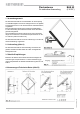
a) Aspettative poste al montante dell’antenna b) Regolazione della polarizzazione I segnali satellitari vengono trasmessi con una determinata direzione, cioè sono «polarizzati». L’antenna piatta BAS 62 è adatta per la ricezione di segnali lineari polarizzati (orizzontali e verticali). Al fine di ottenere una ricezione ottimale con l’antenna, è necessario che venga ev. riaggiustata in dipendenza della posizione geografica relativa a questa polarizzazione.
Pre-regolazione della polarizzazione Türksat 42° Ost ASTRA 19,2° Ost EUTELSAT 28,2° Ost Alantic Bird 3 16° Ost 13° Ost 10° Ost 7° Ost 5° West Albania - - - +10 +12 +15 +18 - Austria -22 +3,5 -3 +2,5 +5 +8 +10 +18 Belgio -25,5 -4,5 -9 -5 -3 -1 +2 +10 Bulgaria -17,5 - - +15 +17 +18 +22 +30 Croazia -23,5 +4,5 -4 +5 +7 +10 +13 +22 Danimarca -19,5 +1,5 -4 0 +3 +5 +6 +12 - - +5 +8 +10 +12 +13 +15 Finlandia Francia Germania Grecia -30 -7,5
d) Collegamento del cavo (figura F) Treccia 1. Preparare il cavo (diametro del mantello: 6,8 mm) come descritto nella figura F e avvitare quindi la presente spina F. Se utilizzate un cavo avente un mantello con un altro diametro, sarà necessario utilizzare una spina F rispettivamente adatta. 2. Allentare le due viti zigrinate della calotta di protezione dell’LNB e rimuoverle. 3. Posare il cavo come mostrato nella figura F e avvitare quindi con il dado a risvolto della spina F all’LNB. 4.
3. Allentare a questo punto un dado a farfalla leggermente nella fascetta di chiusura. Girare l’antenna intorno all’asse del traliccio (Azimut) in direzione del satellite ricercato (orientamento base verso sud), finché viene ricevuto il programma regolato. 4. Stringere a questo punto di nuovo leggermente il dado a farfalla. Adesso l’antenna è centrata in maniera grossolana. 5.
• Come conduttore di terra si addice un filo singolo di rame massiccio con una sezione di almeno 16 mm2, d’alluminio di 25 mm2 o d’acciaio di 50 mm2 o installazioni domestiche di metallo (per esempio tubi di metallo passanti dell’impianto idrico e di riscaldamento), purché corrispondano alla sezione e alla resistenza continua del collegamento elettrico e almeno alle rivendicazioni del conduttore di terra.
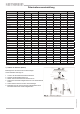
• Tabella Azimut/elevazione Come primo avvicinamento potete utilizzare i satelliti EUTELSAT II F2 10° e per EUTELSAT II F3 16° i valori della tabella del satellite EUTELSAT II F1 13°. I valori riportati nella colonna „U“ (U = giro manovella) si riferiscono ai giri della manovella nell‘utilizzo del sistema BAS 60/61 come antenna mobile e non hanno alcun significato nell‘utilizzo di BAS 62 come antenna stazionaria.
EUTELSAT 13,0° Ost Atlantic Bird 5,0° West ASTRA 28,2° Ost Austria Az El U Az El U Az El U Az El Bregenz 167,28 34,66 4 3/4 175,60 35,34 4 3/4 199,65 33,56 4 3/4 155,7 32,5 5 Graz 174,88 35,78 4 3/4 183,34 35,85 4 3/4 206,99 32,33 5 162,8 34,5 4 3/4 Innsbruck 169,41 35,78 4 3/4 177,80 35,67 4 3/4 201,81 33,38 5 157,6 33,3 5 Klagenfurt 173,32 36,17 4 3/4 181,83 36,37 4 3/4 205,76 33,12 5 161,2 34,7 4 3/4 Lienz 171,21 35,79 4 3/4 179,68 3
EUTELSAT 13,0° Ost Atlantic Bird 5,0° West ASTRA 28,2° Ost Inghilterra Az El U Az El U Az El U Az El U Aberdeen 155,10 22,33 5 3/4 162,19 23,63 5 3/4 183,45 24,93 5 1/2 145,2 19,8 6 Belfast 150,07 23,70 5 3/4 157,17 25,40 5 1/2 178,85 27,73 5 1/4 140,2 20,5 6 Birmingham 154,04 26,86 5 1/2 161,44 28,40 5 1/4 183,88 29,92 5 1/4 143,8 23,8 5 3/4 Bristol 152,93 27,69 5 1/2 160,37 29,34 5 1/4 183,09 31,10 5 142,7 24,5 5 3/4 Glasgow 152,36 23,0
Atlantic Bird 5,0° West ASTRA 28,2° Ost El U Az El U Az El U Az El U Albacete 148,57 39,84 4 1/4 157,18 42,28 4 185,02 44,73 4 137,4 35,2 4 3/4 Algeciras 142,10 40,62 4 1/4 150,49 43,72 4 179,21 48,05 3 1/2 131,5 35,1 4 3/4 Alicante 150,03 41,02 4 1/4 158,86 43,36 4 187,22 45,30 3 3/4 138,6 36,5 4 1/2 Almeria 146,51 41,55 4 1/4 155,27 44,24 4 184,25 47,17 3 3/4 135,4 36,5 4 1/2 Avila 145,75 36,98 4 1/2 153,88 39,60 4 1/4 180,43 43,01