Instruction Manual MSK 25 Satellite/TV/FM Test Receiver analogue/digital
Preface Preface Dear customer, The KATHREIN-Werke KG has done its utmost to guarantee the correctness and completeness of this manual. However, no liability can be assumed for any potential errors in this manual and any damages thereby resulting. This manual may not be copied or else be duplicated, neither as a whole, nor in extracts, without the written consent of the KATHREIN-Werke KG. This manual is subject to modifications and amendments without prior notice.
Contents Contents Preface.............................................................................................................................................................. 2 Contents ........................................................................................................................................................... 3 General Information.........................................................................................................................................
Contents MPEG Picture Representation (option) in DVB-C or DVB-T (option) .......................................................... 40 FM measurement ........................................................................................................................................... 41 Frequency Indication and Frequency Entry ................................................................................................. 41 Level Measurement............................................................
General Information General Information This user manual has been compiled for persons with some electrical engineering ability and knowledge. Users who have already operated similar measuring instruments can obtain the necessary commands for each operating step from the overview. In addition, the following examples will help you understand each operating step.
Functionality The MSK 25 has been conceived as a portable test receiver for TV, SAT and FM radio measurements, as well as for DVB-C, DVB-S and DVB-T in both, battery operation and mains operation. The built-in lead battery (3.4 Ah) and a wall power supply with a built-in charger, suitable for 230 VAC, are included in delivery. Controlling and scanning of the console and the display of frequency and level on the LCD are carried out by a microcontroller. The receiving frequency is indicated in MHz.
* * * * Spectrum display Loudspeaker for acoustics control Multiple standards reception (B/G, D/K, I, L, Nicam, M/N, M1) Nicam audio reception and L standard Sound storage medium setting * * 22 kHz / 60 Hz change-over DiSEqC™, Simple DiSEqC™ Nicam tone, reception and bit error rate measurement * Option MPEG * (audio ) Scart output (video and audio) * Option MPEG DVB displaying * DVB-MER-BER measurement * * * QPSK Option MPEG * * * * DVB-S mode * * * * * * * * * Analogue
LNB 0/5 - 20 V
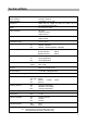
Technical Data Technical Data Power supply Mains operation Battery operation 230 VAC, 50/60 Hz Lead Battery 12 V/3.4 Ah Dimensions Width 260 mm, Height 90 (120) mm, Depth 165 mm incl. accessories (plus case) Weight ca. 4.5 kg (incl. case) Safety standards CE mark Protection class II VDE EN 61010 Display Temperature range Frequency range TFT screen, LCD alpha numeric, 2x16 characters, Bargraph display, backlit SAT TV FM Channel configuration +5 C to +45 C 920 MHz...2150 MHz 48 MHz...
Technical Data TV B/G standard D/K standard I standard M/N standard M1 standard L standard B/G standard I standard TT1 = 5.5 MHz, TT2 = 5.74 MHz TT1 = 6.5 MHz, TT2 = 6.26 MHz TT1 = 6.0 MHz TT1 = 4.5 MHz, TT2 = 4.72 MHz TT1 = 4.5 MHz AM 6.5 MHz, Nicam = 5.85 MHz Nicam = 5.85 MHz Nicam = 6.552 MHz FM FM audio processing 48 MHz...858 MHz Sound carrier measurement TV D/K standard I standard L standard M/N standard M1 standard Nicam decoder Sound carrier distance TV 5.
Control Elements and Indicators Control Elements and Indicators TFT colour screen LC display HF input socket LED volume control Keyboard Control Elements The following is displayed on the two-row 16 digit LC display, depending on the mode: FR: 954.0 MHz LEV: 40.
Short Cut Overview Short Cut Overview Key SAT/TV Brief description of the various functions SAT/DVB-S TV/DVB-C/*DVB-T FM Change-over to Change-over Change-over to TV reception SAT reception TV reception - Diminish current values + Elevate current values 0-9 Numeric character entry .
Connections Connections RF Input Socket The received signal of the antenna or of the cable network is fed in here (BNC coaxial socket). The remote feeding voltage (for LNB) is adjustable from 5 VDC to 20 VDC and can be switched off. When the LNB voltage is switched on, the LED next to the RF input socket flashes. Make sure that there are • no voltage level over 120 dBµV, • no positive DC voltage over 22 VDC, • no negative DC voltage and • no AC voltage adjacent to the RF input socket.
Commissioning Commissioning Switching-Up Software V2.0 SN: 000222 ACCU • Connect the instrument to the mains with the wall power supply. • Turn the on/off switch to the right. • Adjust the desired volume. The LC display will then indicate the particular software version for appr. 1 second. [−−−−−] Thereafter the LC display will indicate the loading capacity of the battery for appr. 3 seconds. One segment comes up to appr. 20% of the overall capacity (3.4 Ah).
Commissioning Setup-Menu The basic setting (status of the MSK 25 after switching it on) can be set in the Setup menu. Factory Setting on Delivery Parameter POWER ON LNB DC LEVEL Low Level Mute Setting TV OFF dBµV ON Setup Menu Setting Setup Menu Call-Up Press [2ndF] and [SETUP]. The particular mode (TV, SAT, FM) is selected and taken-over by pressing either [1], [2] or [3]. The current setting is retained by pressing [ENTER.] POWER ON 1=TV 2=SAT 3=FM 1.
Commissioning Mains Operation and Battery Operation The MSK 25 may either be mains operated or be battery operated (battery built-in). Mains Operation Only the wall power supply delivered may be used for power supply. Connect it to the voltage supply socket on the right hand side of the instrument. Sustained continuous operation (incl. MPEG option) is possible in case of an LNB power consumption of no more than max. 300 mA.
SAT measurement SAT measurement Standard Change-Over In SAT mode, the MSK 25 receives • analogue signals and • DVB-S signals.
SAT measurement Frequency Display and Frequency Entry To measure the level of a received signal, you must first enter the frequency required. The LC display indicates the frequency and the level measured. Frequency entry is possible from 920 MHz to 2150 MHz in 100 kHz steps. ☞ SAT Menu Frequency Entry [SAT/TV] Changing over to SAT reception À [0] to [9] Entering frequency [+] [-] Varying frequency in 100 kHz steps [ENTER] Confirming your entry FR:1288.0MHz LEV: 66.
SAT measurement SAT Analogue Level Measurement Once you have entered a frequency, the level is measured automatically and displayed either in dBµV or dBmV (depending on the basic configuration) on the LC display. The input level can be measured in the range of 30 dBµV to 120 dBµV (-30 dBmV to 60 dBmV). LC display: FR:1508.0MHz LEV: 86.5dBuV SAT A │ • Frequency: 1508 MHz • Mode: SAT • Level measured: 86.5 dBµV A Level Overflow and Level Underflow FR:1508.0MHz LEV: __._dBuV FR:1508.
SAT measurement Locating Satellites With the SCAN function, satellites, the exact transponder frequencies of which are unknown, can be located. In doing so, the frequency range from 1000 MHz to 2100 MHz is continuously scanned for received signals. If signals are received, the reception level is displayed as a bar graph. The measurement range may be adjusted to three different sensitivity levels.
SAT measurement Bearing for Individual Reception Frequencies The „LEVEL ♫“ function allows the antenna alignment to maximum received signal via bearing. The level tendency can be bargraphdisplayed.The measurement range can be adjusted to three different sensitivity levels. The level can be monitored with an acoustic signal, the pitch of which is proportional to the received-signal level. The volume of the directional radio audio signal can be adjusted with the volume regulator.
SAT measurement SAT Analogue Sound Carrier Frequency Each video signal has several sound carrier frequencies assigned to it. Selective hearing of the sound maincarriers and the sound subcarriers is possible. The sound carrier frequency is tunable from 5.0 MHz to 8.99 MHz in 10 kHz steps. The soundcarrier bandwidth is automatically changed over from wide (280 kHz) to narrow (150 kHz) at 7.00 MHz.
SAT measurement DVB-S MER, BER and Offset Measurement The modulation error rate (MER), the bit error rate (BER) and the carrier offset can be measured to rate the digital reception quality. Chapter ‚standard change-over‘ describes how to select between SAT/analogue and DVB-S. Calling up DVB-S measurement: Press [2ndF] [DVB] in SAT reception mode LC display: MER:12.6dB BER:1.7e-7 MHz + 0.72 • (MER) modulation error rate: 12.6 dB • (BER) bit error rate: 1.7e-7 • Carrier offset +0.
SAT measurement LNB Voltage and 22 kHz/60 Hz Change-Over The LNB supply voltage can be obtained from the RF socket. For checking purposes, the LED beside the RF socket flashes when the voltage supply is switched on. The power consumption of the connected LNB is displayed on the LCD. The additionally connectable 22 kHz square-wave signal or the 60 Hz square-wave signal respectively will superimpose the LNB voltage when connected. It is necessary, e. g.
SAT measurement Example ✐ Activating the 22 kHz signal: Press [2nF] [LNB] [8] LC display: LNB:14,0V 150mA 22kHz • LNB voltage: 14 V • Power consumption: 150 mA • 22 kHz signal activated Note By pressing [8] again, the 22 kHz signal can be deactivated. ☞ By calling up a different function, e. g. [2ndF] [CH-FRQ] or 2x [2ndF], the LNB menu will be closed automatically.
SAT measurement DiSEqC™ (Digital Satellite Equipment Control) The DiSEqC™ system is used for control systems with extended control facilities. DiSEqC™ utilises a serial, bidirectional transmission mode with one master and one or more slaves. The data bits are generated with pulse width modulation of the 22 kHz carrier already existent, and are superimposed with 600 mVpp of the LNB remote feeding voltage.
SAT measurement ✐ DiSEqC- Example for a USER entry You wish to check the EXR 22 KATHREIN matrix. The instruction set for the EXR 22 matrix is E0 00 24 (LNB High) and E0 00 20 (LNB Low). Calling up DiSEqC™: Press [2ndF] [SAT-CTRL] Press [0] to call up USER entry. SAT-CTRL menu DiSEqC-Framing E■ You can now enter the indvidual code words by pressing [0] to [9] and [./S]. Press [ENTER] to send the command. „>“ signalises the successful sending of the command.
SAT measurement Address Byte Menu À Hex Byte 00 10 11 12 14 15 18 20 21 22 30 31 32 33 34 40 41 60 70 71 Fx 28 Description All instruments Every LNB, Matrix or SMATV LNB LNB with loop-through Matrix (Switcher) Matrix (Switcher) with loop-through SMATV Every polarizer Maximum turning (full skew) in linear polarisation Stepwise polarizer adjustment Every positioner Polar/Azimuth positioner Elevation positioner Combined positioner LNB Positioner Set up help Signal strength setting help Reserved for assigne
SAT measurement Command Byte Menu MSK 25 can send commands under DiSEqC™ 1.0 but cannot receive them. All the commands requiring DiSEqC™ 2.0 (sending and receiving) are underlined grey in the table below. À Hex Byte Commands in bold are particularly preferred for KATHREIN switching matrices.
SAT measurement 4F 50 51 52 53 58 59 60 61 62 64 65 6C 6D 30 Write A7 LO string LO now LO Lo LO Hi Write Freq Ch.No.
SAT measurement Data Byte Menu À A corresponding data byte need not be sent to a command byte unless required by the command byte data byte(s). You can see this from the preceding command byte table. Please learn from the data sheets of the respective instruments which data byte is to be sent to the particular command byte.
TV measurement TV measurement Standard Change-Over In TV mode, the MSK 25 can measure the following standards: • B/G standard • L standard • D/K standard • I standard • M/N standard • M1 standard (Japan) Standard Change-Over TV Menu À [2ndF] [STD] Calling up standard change-over menu [0] Addressing standard menu [0] bis [6] Selecting standard Example ✐ Calling upB/G analogue standard: Press [2ndF] [STD]. LC display: 1=ANALOG 3=DVBT 2=DVBC 0=Std.
TV measurement DVB-C/DVB-T Change-Over Press [2ndF] [STD]. LC display: 1=ANALOG 3=DVBT 2=DVBC 0=Std. • 1 = Analogue reception • 2 = DVB-C reception • 3 = DVB-T reception (if this option is provided) • 0 = Standard menu Press [2] to change over to DVB-C standard LC display: 1=QAM64 3=DOC64 2=QAM128 • 1 = QAM 64 demodulation • 2 = QAM 128 demodulation • 3 = DOCSIS QAM 64 demodulation Press [1] to set the QAM 64 symbol rate 1=6.900 3=6.875 2=6.952 4=USER LC display: • 1 = 6.
TV measurement Channel display and channel entry You first have to set the required channel to be able to measure the level of a TV reception signal. The following channels may be set: • Band /III CH 01 to CH 12 in 7 MHz raster • Band IV/V CH 21 to CH 70 in 8 MHz raster • Special channel S 02 to S 03 in 8 MHz raster • Special channel S 04 to S 20 in 7 MHz raster • Special channel S 21 to S 41 in 8-MHz raster This information applies only for the factory-set B/G standard.
TV measurement Frequency Display and Frequency Entry You first have to enter the required picture carrier frequency to be able to measure the level of a TV reception signal. Frequency entry is possible from 48 MHz to 858 MHz in 50 kHz steps. TV Frequency Entry Mode À [SAT/TV] Changing over to TV reception [CH-FRQ] Change-over channel/frequency [0] bis [9] Entering frequency [ENTER] Confirming entry [+] und [-] Varying frequency stepwise Example Entering frequency 175.
TV measurement Level Measurement TV Analogue After you have set a channel or a frequency, the level is automatically measured and displayed on the LC display either in dBµV or in dBmV (depending on the basic configuration). The input level can be measured in the range of 30 dBµV to 120 dBµV (-30 dBmV to 60 dBmV). LC display: CH: .05. LEV: 86.5dBuV TV A • Channel: CH 05 • Mode: TV analogue • Level measured: 86.
TV measurement Bearing for Individual Reception Frequencies The „LEVEL ♫“ function allows the antenna alignment to maximum received signal via bearing. The level tendency can be bargraphdisplayed. The measurement range can be adjusted to three different sensitivity levels. The level can be monitored with an acoustic signal, the pitch of which is proportional to the received-signal level. The volume of the directional radio audio signal can be adjusted with the volume regulator.
TV measurement Sound Carrier Distance and Sound Carrier Level On a second sound carrier, TV broadcast stations can transmit either frequency-modulated (analogue) or in Nicam format (digital). Depending on the standard which has been set, various frequencies are assigned to the sound carriers, see table. Sound carrier 1 is permanently set after the channel entry or frequency entry. Standard B/G D/K I M/N L M1 (Japan) TT1 5.5 MHz 6.5 MHz 6.0 MHz 4.5 MHz AM 6.5 MHz 4.5 MHz TT2 5.74 MHz 6.26 MHz -----4.
TV measurement Press [3] while the sound carrier is displayed Note The sound carrier frequency is not adjustable but changed over according to the standard which has been set. ☞ The sound carrier level is only displayed when key [2] or [3] is pressed. NICAM Sound Bit Error Rate Measurement The bit error rate may be measured for an improved evaluation of the Nicam signal sound quality. Example ✐ SC: 5.85 MHz BER=2.
TV measurement DVB-C/DVB-T (option), MER, BER and Offset Measurement The modulation error rate (MER), the bit error rate (BER) and the carrier offset can be measured to evaluate the quality of the digital reception. Chapter ‚standard change-over‘ describes how to select either TV analogue, DVB-C or optionally DVB-T. Calling up DVB-C/DVB-T (option) measurement: Press [2ndF] [DVB] LC display: MER:30.5dB BER:2.0e-8 MHz 0.00 • Modulation error rate (MER): 30.5 dB • Bit error rate (BER): 2.
FM measurement FM measurement Frequency Indication and Frequency Entry You first have to enter the desired frequency to be able to measure the level of an FM reception signal. Frequency entry is possible from 48 MHz to 858 MHz in 50 kHz steps. FM Frequency Entry Menu À [2ndF] [FM] Changing over to FM reception [0] bis [9] Entering frequency [ENTER] Confirming entry [+] und [-] Varying frequency in 50 kHz steps Example Entering frequency 99.25 MHz: ✐ Press [2ndF] [FM]..........................
FM measurement Level Measurement After you have set a frequency, the level is automatically measured and displayed in dBµV. The input level can be measured in the range of 30 dBµV to 120 dBµV. LC display: Fr:104.80MHz LEV: 86.5dBuV FM A │ • Frequency: 104.8 MHz • Mode: FM • Level measured: 86.5 dBµV Level Overflow and Level Underflow The LC display indicates underflow at a level of < 30 dBµV. LC display: FR:104.80MHz LEV: ___._dBuV FM A │ • Frequency: 104.
FM measurement Bearing for Individual Reception Frequencies The „LEVEL ♫“ function allows the antenna alignment to maximum received signal via bearing. The level tendency can be bargraphdisplayed. The measurement range can be adjusted to three different sensitivity levels. The level can be monitored with an acoustic signal, the pitch of which is proportional to the received-signal level. The volume of the acoustic signal can be adjusted with the volume regulator.
Spectrum Measurement Spectrum Measurement The frequency spectrum in the SAT, TV and FM modes may be displayed on the TFT screen for evaluation purposes. You can call up the function ‚spectrum measurement‘ in each particular mode (SAT, TV, FM). Command for ‚spectrum measurement‘: [2ndF] [Spect]. Back to the regular LC display: 2 x [2ndF]. By pressing [-] and [+], you can move a cursor ▽ on the level curve in order to measure certain level minima and level maxima.
Spectrum Measurement TV Spectrum Menu À LC displays and range setting: [1] FULL SPAN = overall TV range (48…858 MHz) [2] VHF (48…467 MHz) UHF [3] UHF (467…858 MHz) TV-Narrow [4] NARROW (634…659 MHz) TV-Full VHF FM Spectrum The FM spectrum is addressed and measured as described above. It ranges from 87 MHz to 108 MHz.
Maintenance Maintenance Changing the Battery • Unscrew the two screws which fix the straps on the leather bag.Then unscrew the screw in the leather cap. Pull the receiver out of the leather bag. • Now unscrew all the screws atop, at the bottom and on every side of the metal box. Pull the receiver out of it. • Unscrew the two screws on the left and on the right of the DVB 25 circuit board mounting, and turn the DVB 25 circuit board upright. • Disconnect the battery poles.
Technical Appendix Technical Appendix Signal-to-Noise-Ratio The following values must be known in order to determine the carrier/signal-to-noise-ratio (C/N): • Basic noise level (adjust the dish antenna so that no satellite signal will be received) • Maximum reception level • Bandwidth correction The following formula applies: C/N = Received signal level – Basic signal-to-noise-ratio – Bandwidth correction 6 MHz (Measurement bandwidth MSK 25) Bandwidth correction value = 10 log ---—————————————–-RF b
Technical Appendix DiSEqC™ Commands for Kathrein Matrices Instruction Set for 9xx Kathrein Matrix Production Run POS. A (Satellit 1) Range DiSEqC™ Command Low-Band High-Band Vert. Horiz. Vert. Horiz. F0 00 38 F0 F0 00 38 F2 F0 00 38 F1 F0 00 38 F3 POS. B (Satellit 2) Range DiSEqC™ Command Low-Band High-Band Vert. Horiz. Vert. Horiz. F0 00 38 F4 F0 00 38 F6 F0 00 38 F5 F0 00 38 F7 Instruction Set for EXR 20 Kathrein Matrix EXR 20 Range DiSEqC™ Command POS. A POS.
Technical Appendix Channel Tables Channel Table and Frequency Table B/G Standard (frequencies in MHz) VRF-CCIR URF-CCIR URF-CCIR Pilot frequency 01 80.15 21 21 471.25 46 46 671.25 E2 02 48.25 22 22 479.25 47 47 679.25 E3 03 55.25 23 23 487.25 48 48 687.25 E4 04 62.25 24 24 495.25 49 49 695.25 E5 05 17.25 25 25 503.25 50 50 703.25 E6 06 182.25 26 26 511.25 51 51 711.25 E7 07 189.25 27 27 519.25 52 52 719.25 E8 08 196.25 28 28 527.
Technical Appendix Channel Table and Frequency Table L Standard (frequencies in MHz) VHF * LB * LC * LC1 L1 L2 L3 L4 L5 L6 K14 K15 K16 K17 K18 K19 01 02 03 04 05 06 07 08 09 10 11 12 13 14 15 16 17 18 19 20 UHF 80.75 55.75 60.50 63,75 176.00 184.00 192.00 200.00 208.00 216.00 308.75 441.75 861.75 175.25 183.25 191.25 199.25 207.25 215.25 223.25 UHF 21 22 23 24 25 26 27 28 29 30 31 32 33 34 35 36 37 38 39 40 41 42 43 44 45 21 22 23 24 25 26 27 28 29 30 31 32 33 34 35 36 37 38 39 40 41 42 43 44 45 471.
Technical Appendix Channel Table and Frequency Table D/K Standard (frequencies in MHz) VHF R-I R-II R-III R-IV R-V R-VI R-VII RR-IX R-X R-XI R-XII 01 02 03 04 05 06 07 08 09 10 11 12 13 14 15 16 17 18 19 20 UHF 49.75 59.75 77.25 85.25 93.52 175.25 183.25 191.25 199.25 207.25 215.25 223.25 50.00 60.00 70.00 75.00 80.00 90.00 175.00 200.00 UHF 21 22 23 24 25 26 27 28 29 30 31 32 33 34 35 36 37 38 39 40 41 42 43 44 45 21 22 23 24 25 26 27 28 29 30 31 32 33 34 35 36 37 38 39 40 41 42 43 44 45 471.
Technical Appendix Channel Table and Frequency Table I Standard (frequencies in MHz) VHF IA IB IC ID IE IF IG IH IJ 01 02 03 04 05 06 07 08 09 10 11 12 13 14 15 16 17 18 19 20 UHF 45.75 53.75 61.75 175.25 183.25 191.25 199.25 207.25 215.25 223.25 231.25 239.25 247.45 50.00 60.00 70.00 75.00 80.00 90.00 175.00 UHF 21 22 23 24 25 26 27 28 29 30 31 32 33 34 35 36 37 38 39 40 41 42 43 44 45 21 22 23 24 25 26 27 28 29 30 31 32 33 34 35 36 37 38 39 40 41 42 43 44 45 471.25 46 479.25 47 487.25 48 495.
Technical Appendix Channel Table and Frequency Table M1 Standard (Japan) (frequencies in MHz) VHF J01 J02 J03 J04 J05 J06 J07 J08 J09 J10 J11 J12 01 02 03 04 05 06 07 08 09 10 11 12 S1 S2 S3 S4 S5 S6 S7 S8 S9 S10 S11 S12 S13 S14 S15 S16 S17 S18 S19 UHF 91.25 97.25 103.25 171.25 177.25 183.25 189.25 193.25 199.25 205.25 211.25 217.25 UHF 13 13 471.25 14 14 477.25 15 15 483.25 16 16 489.25 17 17 495.25 18 18 501.25 19 19 507.25 20 20 513.25 21 21 519.25 22 22 525.25 23 23 531.25 24 24 537.25 25 25 543.
Technical Appendix Channel Table and Frequency Table M/N Standard (frequencies in MHz) VHF A02 A03 A04 A05 A06 A07 A08 A09 A10 A11 A12 A13 01 02 03 04 05 06 07 08 09 10 11 12 13 72.00 55.25 61.25 67.25 77.25 83.25 175.25 181.25 187.25 193.25 199.25 205.25 211.25 UHF 14 15 16 17 18 19 20 21 22 23 24 25 26 27 28 29 30 31 32 33 34 35 36 37 38 39 40 41 42 43 44 45 46 14 15 16 17 18 19 20 21 22 23 24 25 26 27 28 29 30 31 32 33 34 35 36 37 38 39 40 41 42 43 44 45 46 UHF 471.25 477.25 483.25 489.25 495.
Technical Appendix Channel Table and Frequency Table M/N Standard (frequencies in MHz) Special channels A-5 95 S01 A-4 96 S02 A-3 97 S03 A-2 98 S04 A-1 99 S05 A 14 S06 B 15 S07 C 16 S08 D 17 S09 E 18 S10 F 19 S11 G 20 S12 H 21 S13 I 22 S14 J 23 S15 K 24 S16 L 25 S17 M 26 S18 N 27 S19 O 28 S20 P 29 S21 Q 30 S22 R 31 S23 S 32 S24 T 33 S25 U 34 S26 V 35 S27 W 36 S28 AA 37 S29 BB 38 S30 CC 39 S31 DD 40 S32 EE 41 S33 FF 42 S34 GG 43 S35 HH 44 S36 II 45 S37 JJ 46 S38 KK 47 S39 LL 48 S40 MM 49 S41 NN 50 S42 91.
936.2642/D/1005/ZWT Subject to technical modifications. internet http://www.kathrein.