
Satellite/TV/FM Test Receiver Instruction Manual

Connections
13
Connections
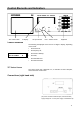
RF Input Socket
The received signal of the antenna or of the cable network is fed in here
(BNC coaxial socket).
The remote feeding voltage (for LNB) is adjustable from 5 V
DC
to 20 V
DC
and can be switched off. When the LNB voltage is switched on, the LED
next to the RF input socket flashes.
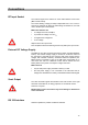
Make sure that there are
• no voltage level over 120 dBµV,
• no positive DC voltage over 22 V
DC
,
• no negative DC voltage and
• no AC voltage
adjacent to the RF input socket.
Non-compliance with these warning notices may destroy the input circuit.
External DC Voltage Supply
The MSK 25 may either be mains operated or battery operated (batteries
built-in). The external voltage supply is carried out via the DC socket at
the right side of the MSK 25 box, with the wall power supply and the
charger, both included in delivery. Sustained continuous operation (incl.
MPEG option) is possible in case of an LNB power consumption of no
more than max. 300 mA. Additional current will be drained from the
battery built-in if the power consumption is higher than that.
Make sure that
• only the wall power supply included in delivery is used.
• the wall power supply is not connected to the instrument but for
voltage feed. Otherwise the battery of the MSK 25 will be discharged!
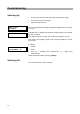
Scart Output
The video and audio signals are emitted on the Scart socket on the right
hand side of the MSK 25, for rating purposes on an external monitor.
There are no inputs!
Misallocations of the connections may cause damage or destruction
of the instrument!
RS 232 Interface
Software updates are possible via RS 232 interface.