Operator's manual Video Sweep Generator MVG 10 Order no.
Preface Preface Dear customer, This handbook aims to help you use the various functions of the MVG10 in the optimal manner. Please pay attention to all instructions. Kathrein-Werke KG has made every effort to ensure the information and descriptions are correct and complete. We reserve the right to make changes to this handbook without prior notice. In particular, this applies to changes made due to technical advancements. We are always grateful to receive your comments and suggestions for improvement.
Contents Contents Preface .....................................................................................................................................................3 Contents ...................................................................................................................................................5 Safety notes..............................................................................................................................................6 Safety notes........
Safety notes Safety notes Validity of handbook This handbook is valid for MVG 10, order no.: 208 320. The following notes are important for operating the MVG 10 and should be observed under all circumstances. General safety notes The MVG 10 was developed and produced in compliance with the relevant harmonised guidelines, standards and additional technical specifications. The product is state-of-the-art and ensures the maximum level of safety.
Safety notes Safety notes Always observe the VDE safety regulations. Observe the maximum permissible signal feed-in level. Neither DC voltage nor low-frequency AC voltage may be applied to the RF port. Only use fuses with the same cut-out characteristics. The unit is live even when not connected. The unit may only be operated with all shielding covers fitted and when closed to prevent electromagnetic interference. Only use suitable shielded cable.
System description and usage System description and usage The MVG 10 Video Sweep Generator is designed to selectively sweep and measure the forward path and return path of television cable installations without interfering with the connected subscribers. The required sweep ranges, channels and signal levels (36…100 dBµV) can be programmed step-by-step. The channels can be set to various standards (e.g. B/G etc.).
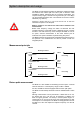
System description and usage Downstream measurement: 47…860 MHz Head-end (or transfer point) Transfer point (or terminal outlet) Cable installation MVG 10 Sweep generator MSK 33 receiver with return path-capable amplifiers Upstream measurement: 4.0…80 MHz Head-end (or transfer point) Transfer point (or terminal outlet) Cable installation MSK 33 receiver with return path-capable amplifiers MVG 10 Sweep generator Comfortable upstream 4.
System description and usage The spectrum at the head-end can be printed out from the MSK 33 (1) using the print command "Prt 999" on the MVG 10 (1). The command "Clear" clears the spectrum presentation on the MSK 33 (1). Downstream measurement: The MVG 10 (2) is switched from signal generator mode to downstream sweep generator mode via the MSK 33 (1) using the command "Fkt A 1" on the MVG 10 (1). The MVG 10 (2) sweeps the forward path in the free frequency ranges.
Views, connections and controls Views, connections and controls Left-hand side Scart socket Right-hand side RS232 socket Frontal view RF output 11 Display Keypad Power supply
Button functions Button functions The following information explains the operation of the MVG 10. Please use the illustration of the operating concept for assistance. Button Function Display On 1. Switch on unit when depressed briefly The upper display appears first, then the lower display with the last function that was set Off 2.
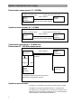
System settings System settings We recommend checking the factory settings before initial start-up. Please use the operating concept on page 2 for help with understanding the operating sequence. Function Button actuation Switch on unit when depressed briefly On The upper display appears first, then the lower display shortly afterwards with the last function that was set Select "System" main function and show battery charge state KATHREIN MVG10 Off NG Store nr: 0 System...
System settings Display units ▼ W X + Sys Unit dBµV (dBmv, dBm) - + System baud rate ▼ Sys Baudr: 19.2k setting not possible Transmission readiness ▼ Sys RTS/CTS on setting not possible Confirm entries Menu Select 14 System..
Noise generator Noise generator The noise generator is used for measuring cable installations or sections of cable installations that are not yet occupied with programming. It generates a broadband noise to evaluate the frequency response in the range from 4 MHz to 1 GHz. The bandwidth can be set to 1 MHz or 7/8 MHz.
Signal generator Signal generator The signal generator is needed to transmit test signals and the screen view from the MSK 33 during "Comfortable Up/Downstream measurement" (see system description). In addition to an internal test picture of coloured bars it has an external modulation input (CVBS/RGB + sound) and is double-sideband modulated. The channels/frequencies and levels can be selected freely.
Signal generator Enter transmission frequency directly followed by "Enter" Channel frequency inputs with incorrect entries after the point are not accepted! Channel entry special channels with press or 0 see above 9 ▼ W X + · SG Channel C __ - + S-Ch first! or Enter channel number directly special channels with press · S-Ch first! Also switch back to normal channel entry with Set standards B/G, D/K, I, M, Mj, H 0 see above 9 · S-Ch ▼ W X + SG Standard B/G - + Set modulation int-AV,
Sweep generator Sweep generator The sweep generator is used to sweep in 10 preset frequency ranges (measuring profiles). The profiles can be programmed to free ranges depending on the channel allocation in the cable network, so that measurement is possible without interrupting or interfering with programmes. The frequencies and levels can be selected freely. Only use the sweep generator on free channels so that programmes and services in the cable network are not interrupted.
Sweep generator ▼ W X SwG FreqRange X Start XXX.XX MHz + Enter start frequency - + or Enter frequency directly 0 Enter end frequency see above 9 ▼ SwG FreqRange X Stop XXX.XX MHz W X + - + or Enter frequency directly 0 50-kHz steps from one frequency to next in MHz see above 9 ▼ W X SwG FreqRange X Step X.
Sweep generator Clear screen presentation on MSK 33 with "Enter" ▼ X + SwG ControlData Clear no run + + Command to clear spectrum received by MSK33 (MVG10 tracking) Enter control printout number (up to 3 digits), confirm with "Enter" and run with "Enter" Command to switch a second MVG10 to stored position "Recall 1" via MSK33 (MSK33 and MVG10 connected via SCART) Command to switch the MSK33 video signal from internal graphics to ext. CVBS.
SwG FreqRange 1 Start 15.00 MHz SwG FreqRange 1 Stop 30.00 MHz SwG FreqRange 1 Step 5.00 MHz SwG FreqRange 0 Start 4.00 MHz SwG FreqRange 0 Stop 10.00 MHz SwG FreqRange 0 Step 2.00 MHz SwG Level 60.0 dBµV SwG Store nr: 9 (0...9) SwG ControlData Clear no run SwG SelRange 0129............. run SwG Tracking no SwG StepTime 150 ms SwG FreqRange 2 Step 20.00 MHz SwG FreqRange 2 Stop 60.00 MHz SwG FreqRange 2 Start 40.
Channel sweep generator Channel sweep generator The channel sweep generator is used to sweep in 10 preset ranges. The channels can be programmed to free ranges depending on the channel allocation in the cable network, so that measurement is possible without interrupting or interfering with programmes. The channels and signal levels can be selected freely. Only use the channel sweep generator on free channels so that programmes and services in the cable network are not interrupted.
Channel sweep generator Enter start channel Special channels with press · ▼ W X + CSw ChanRange X Start C 12 - + S-Ch first! or Enter channels directly 0 Enter end channel Special channels with press · see above 9 ▼ W X + S-Ch first! - + CSw ChanRange X Stop C 30 or Enter channels directly 0 Also switch back to normal channel entry with Channel steps (skip a previously defined number of channels) 9 see above · S-Ch ▼ W X + - + CSw StepChan X Step X or Enter channel steps
Channel sweep generator Set standards B/G, D/K, I, M, Mj, H ▼ W X + CSw Standard B/G - + Set the pre-programmed channel ranges to be processed (0…9) ▼ CSw SelRange ……… no run/run received by MSK33 (MVG10 tracking) ▼ CSw ControlData Clear run Enter control printout number (up to 3 digits), confirm with "Enter" and run with "Enter" X Command to clear spectrum + + Command to switch a second MVG10 to stored position "Recall 0" via MSK33 (MSK33 and MVG10 connected via SCART) Command to switch a sec
CSw ChanRange 1 Start C06 CSw ChanRange 1 Stop C010 SwG FreqRange 1 Step 2 CSw ChanRange 0 Start C02 CSw ChanRange 0 Stop C04 SwG FreqRange 0 Step 1 CSw Store nr: 3 (0...9) CSw ControlData Clear no run CSw SelRange 0129..............
Recall Recall The "Recall" setting is used to call up the setting stored at addresses 0…9 and start the measuring process. Please use the operating concept on page 2 for help with understanding the operating sequence. Function Button actuation Switch on unit when depressed briefly On The upper display appears first, then the lower display shortly afterwards with the last function that was set Select "Recall" main function and no.
Technical appendix Technical appendix Technical data Frequency range: 4.0 MHz...1000 MHz Frequency adjustment: 50 kHz Frequency resolution: 62.5 kHz Display: LCD alphanumeric 2 x 16 characters, bar chart; illuminated Adjustment: direct frequency and channel entry; +/- step buttons Sweep ranges: 10 ranges with start/stop and frequency step entry Channel hopping: 10 ranges with start/stop and channel step entry Output signal level: 36 dBµV ...
936.2879/-/1105/ZWT/e Technical data subject to change. Internet: www.kathrein.de KATHREIN-Werke KG phone +49 8031 184-0 Fax +49 8031 184-306 Anton-Kathrein-Straße 1-3 P.O.