Operating Instructions Part 1 Connection and set-up UFS 946/CI+ English Safety instructions - important notes ............. 2 Troubleshooting ............................................. 47 Product return/original packaging .................... 4 Service ............................................................. 48 Fan/ventilation slots on the unit ........................ 4 Switching the receiver off ................................. 4 Other .......................................................
Safety instructions - important notes These two pages contain important information about the operation, installation location and connection of the unit. Read these instructions carefully before setting up the device. Mains power cable Danger! If the mains voltage is too high, there is a risk of fire! Make sure that the mains cable (power supply cable) is not damaged.
Safety instructions - important notes Installation location Do not place any objects on top of the unit. Unless stated to the contrary in the “Connection and setup” and “Installation” sections in the instructions supplied, maintain a clearance of at least 10 cm above the unit, 2 cm to either side and 5 cm behind the unit, to allow unobstructed dissipation of the heat generated. All electronic equipment generates heat. The temperature rise of this unit does however lie within the permissible range.
Safety instructions - important notes Product return/original packaging Please keep the original packaging in case you need to return the product at any time! The receivers are fragile due to their construction and are only adequately protected by the original packaging. If the receiver is not shipped correctly the guarantee/warranty on it will be voided. Fan/ventilation slots on the unit Make sure that the ventilation slots on the unit are not blocked or covered in any way.
Items supplied ■ UFS 946/CI+ ■ Power supply unit 230 V/12 V ■ Remote control RC 675 ■ 2 batteries AAA 1.
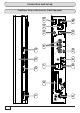
Connection and set-up 6 16 12 8 5 1 6 2 7 3 9 4 10 11 13 14 15 Front/rear view of the receiver (front flap open)
Connection and set-up Front view: Rear view: 1. On/Off button (operation/standby) 5. LNB input (IF INPUT) 2. Channel selection (P-) 6. 3. 16 character display Common Interface for fitting one CI+/CI module for Pay TV cards *) 4. Channel selection (P+) 7. Network connection (Ethernet) 8. USB 2.0 port (USB-A connector) 9. HDMI connection 10. Video output (CVBS) cinch socket 11. Audio outputs (L/R) cinch sockets 12.
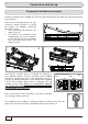
Connection and set-up Suspended installation (example) Remove the wood screws supplied from their transport attachment on the top of the respective mounting piece (2 pieces). Place the two mounting pieces on your receiver as shown in Figures 1-3. During the process the following should be taken into account: 1. Left (L) and Right (R) markings (see arrows Figure 2) 2.
Connection and set-up Installation on a fixed flat surface So as to prevent the receiver slipping or falling, the mounting kit can also be attached to the underside of the receiver. Assembly is the same as for suspended installation, except that the mounting kit is attached to the underside of the receiver. Inserting batteries into the remote control Remove the cover on the rear of the remote control. Insert the two batteries supplied into the remote control.
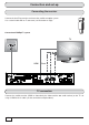
Connection and set-up Connecting the receiver Connect the Sat IF input on the receiver to the satellite reception system. Use a coaxial cable with an F connector (see illustration on right). Conventional DiSEqC™ system TV HDMI Cinch TV connection Connect the satellite receiver (HDMI or alternatively the video and the two audio sockets) to the TV set using a HDMI or cinch cable (see the connection example above).
Connection and Set-Up Audio connection Digital There are two ways you can access the digital audio. HDMI The stereo audio is transmitted to your TV set via the HDMI interface. If your TV set also supports Dolby Digital, you can also receive the Dolby Digital audio via the HDMI interface (providing it is broadcast by the channel provider). Refer to the operating instructions for your TV set for more information.
Connection and set-up First installation Before you start to use the UFS 946/CI+, read the sections “Safety instructions - Important notes” and “Connection and set-up” through to the item “First installation”. Do not connect the unit to the mains until all installation work has been properly carried out.
Connection and set-up Press the (green) button to move to the next menu. The following on-screen display appears: Use the buttons here to select the basic settings for the video and audio output of the receiver to the TV set. For this, refer to the operating instructions for your TV set and take care to select only those settings that your TV set can process. Video Output via The rear panel outputs video via the HDMI socket on the unit's rear panel.
Connection and set-up Show 4:3 Event Here you can select the type of screen display mode for 4:3 broadcasts on a 16:9 TV set. Either - Normal (Pillarbox) - Stretched (full screen) or - Zoom in (Pan & Scan) Audio Format via HDMI Here you can select the type of audio signal that is transmitted by the HDMI interface. Select the signal that your TV set can process: - PCM (Stereo) or - S/PDIF format (multichannel) Auto.
Connection and set-up The following on-screen display appears: Tip! If your receiver is connected up as in the connection example (see the illustration in “Connecting the receiver” in this section), only one change/selection is necessary in the rest of the first installation. If you are not familiar with the details of your reception system, note the following: In many cases the satellite reception system is a DiSEqC™1.0 system. This type of system is preset.
Connection and set-up DiSEqC™1.0 Press the (green) button. The following on-screen display appears: Tuner Configuration (select satellites) Select the number of satellites present in the signal at the tuner (four max.). Go to the “Satellite 1: .....”. Press the button. The following on-screen display appears (example): Configuration Satellite 1 Define the settings for the first satellite for Tuner 1 here. Satellite: buttons.
Connection and set-up - Universal Refer to the documentation for your LNB or seek assistance from a specialist engineer. - Simple or - User-defined If you do not use a Universal LNB, press the (simple or user-defined). button. You can now define the settings for your LNB type LNB Frequencies (MHz): Enter the LNB frequencies (Low/High/Limit) using the number pad. Now use the new values.
Connection and set-up DiSEqC™1.1 Press the (green) button. The following on-screen display appears: Tuner Configuration - Tuner 1 On the “Satellite” line, select the first satellite location. You can use/assign up to 64 satellite locations. Now go to the next line. Press the button. The following on-screen display appears: Satellite: buttons.
Connection and set-up - Universal Refer to the documentation for your LNB or seek assistance from a specialist engineer. - Simple or - User-defined If you do not use a Universal LNB, press the (simple or user-defined). button. You can now define the settings for your LNB type LNB Frequencies (MHz): Enter the LNB frequencies (Low/High/Limit) using the number pad. Now use the new values.
Connection and set-up The receiver will automatically display the screen for the channel search. Continue the first installation with the “Channel search” section. Motorized antenna (DiSEqC™1.2/DiSEqC™1.3 (USALS)) Press the (green) button. The following on-screen display appears: Select the type of motor control suitable for your reception system. Refer to the documentation for your reception system or seek assistance from a specialist engineer.
Connection and set-up Motorized antenna (DiSEqC™1.2) Go to Null Position Select the “Go to Null Position” selection field. Press the its null position. button to instruct the turntable to move to Set Borders Select the “Set Borders” selection field. In this menu you can set the borders for your turntable. This is particularly necessary if the turntable has only a restricted range in which it may turn before striking an obstruction (such as a wall or tree). Press the button.
Connection and set-up If you subsequently want to delete the set borders, switch to the “Reset border positions” field and press button to confirm deletion of the borders. You can then set new values for the limits. Once you have set all the borders, press the button. the Select Satellites - Tuner 1 Go to the “Select Satellites” line. Press the button. The following on-screen display appears (example): Here, select up to 64 satellites to be included in the signal on the tuner.
Connection and set-up On the “Satellite” line select the satellite whose settings you wish to edit. Satellite: buttons. Alternatively you can press the button to Select the desired satellite using the view a list of all satellites which you have previously selected, then select the required satellites from this list. LNB Type: buttons to select the LNB types If your reception system does not have a universal LNB, use the that are used in your reception system.
Connection and set-up Rotate to the East step by step Start slow rotation to the East Set the turntable so that both of the bars “Signal-Strength” and “Signal-Quality” on the right of the screen show the highest available percentage values. When you have reached the best possible signal strength, move to the “Store actual position” line and button. The receiver will now save these values for this satellite and skip automatically press the to the setting for the next satellite.
Connection and set-up Motorized antenna (DiSEqC™1.3) My Longitude Select the field “My Longitude” and use the number pad here to enter your actual longitude. My Latitude Select the “My Latitude” field and use the number pad to enter your actual latitude. Go to Null Position Select the “Go to Null Position” selection field. Press the its null position. button to instruct the turntable to move to Set Borders Select the “Set Borders” selection field.
Connection and set-up If you subsequently want to delete the set borders, switch to the “Reset border positions” field and button to confirm deletion of the borders. You can then set new values for the limits. Once you have set all the borders, press the button. press the Select Satellites - Tuner 1 Go to the “Select Satellites” line. Press the button. The following on-screen display appears (example): Here, select up to 64 satellites to be included in the signal on the tuner.
Connection and set-up On the “Satellite” line select the satellite whose settings you wish to edit. Satellite: buttons. Alternatively you can press the button to Select the desired satellite using the view a list of all satellites which you have previously selected, then select the required satellites from this list. LNB Type: buttons to select the LNB types If your reception system does not have a universal LNB, use the that are used in your reception system.
Connection and set-up Simple LNB Press the (green) button. Satellite: buttons. Alternatively you can press the Select the desired satellite using the view a list of all stored satellites then select the required satellites from this list. button to LNB Type: buttons to select the LNB types If your reception system does not have a universal LNB, use the that are used in your reception system.
Connection and set-up LNB Frequencies (MHz): Enter the LNB frequencies (Low/High/Limit) using the number pad. Now use the new values. button to save the Test-Transponder: Select the “Test-Transponder” field. Here you can select a transponder for checking whether your settings are correct using the signal strength bar and signal quality bar. When you have completed all settings, press the (green) button. The receiver will automatically display the screen for the channel search.
Connection and set-up BAS 60 inkl. HDZ 60 Press the (green) button. Refer to the documentation included with your mobile reception system or seek assistance from a specialist engineer. Position determination: Select here whether you want to undertake position determination by - List selection (current location is selected from a saved list) or - Using GPS data (GPS data on the current location can be entered). List selection Country: Select your current country using the City: buttons.
Connection and set-up Satellite: buttons. Alternatively you can press the Select the desired satellite using the view a list of all stored satellites then select the required satellites from this list. button to Transponder Frequency: buttons. Alternatively you can press the button Select the desired transponder using the to view a list of all transponders stored for this satellite and then select the required transponder from this list.
Connection and set-up OneCable system Select the “Yes” option using the buttons on the “OneCable System Used” line. Now go to the selection field “Tuner 1 & 2: OneCable System”. Press the (green) button. Refer to the documentation for your reception system or seek assistance from a specialist engineer. In the reception system field select the OneCable system in use: - EXR .../EXU ...
Connection and set-up OneCable system - EXR .../EXU ... ...” Use the “EXR .../EXU buttons to select on the “Configure System” line. Press the (green) button. The following on-screen display appears: Saving channel with PIN code: If your single-cable system allows the transmission frequency to be protected by entering a PIN, this can be done in this menu. No other receiver can then use this transmission frequency unless the PIN is input. Select “Yes”.
Connection and set-up Number of Satellites Select the number of satellites present in the signal at Tuner 1 (two max.). Select the line “Satellite 1: .....”. To set or change the currently selected satellite, button. The following press the on-screen display appears (example): On the “Satellite” line select the satellite whose settings you wish to edit. Satellite: buttons.
Connection and set-up LNB Frequencies (MHz): Enter the LNB frequencies (Low/High/Limit) using the number pad. Now use the new values. button to save the Test-Transponder: Select the “Test-Transponder” field. Here you can select a transponder for checking whether your settings are correct using the signal strength bar and signal quality bar. When you have completed all settings for the selected satellites, press the button.
Connection and set-up When you have completed all settings, press the button. Number of Satellites Only one satellite can be received with the UAS 481. This setting cannot be altered. Select the line “Satellite 1: .....”. To set or change the currently selected satellite, button. The following press the on-screen display appears (example): Satellite: buttons.
Connection and set-up OneCable system - User-defined Use the buttons to select “Userdefined” on the “Configure System” line. Press the (green) button. The following on-screen display appears: Saving channel with PIN code: If your single-cable system allows the transmission frequency to be protected by entering a PIN, this can be done in this menu. No other receiver can then use this transmission frequency unless the PIN is input. Select “Yes”.
Connection and set-up Number of Satellites Select the number of satellites present in the signal at Tuner 1 (two max.). Select the line “Satellite 1: .....”. To set or change the currently selected satellite, button. The following press the on-screen display appears (example): On the “Satellite” line select the satellite whose settings you wish to edit. Satellite: buttons.
Connection and set-up LNB Frequencies (MHz): Enter the LNB frequencies (Low/High/Limit) using the number pad. Now use the new values. button to save the Test-Transponder: Select the “Test-Transponder” field. Here you can select a transponder for checking whether your settings are correct using the signal strength bar and signal quality bar. When you have completed all settings for the selected satellites, press the button.
Connection and set-up Channel search If you do not wish to perform a channel search, press the section “Time setting”. If you wish to perform a channel search, use the (green) button and continue with the buttons to select “Yes”. The following on-screen display appears: Country Select buttons, select Using the whether the channels found after the search are to be sorted using a factory channel list for the selected country.
Connection and set-up To view encrypted channels you need an appropriate CI (Common Interface) module and a valid Smartcard together with a valid subscription to the relevant Pay TV provider. Network Search (NIT) buttons (On/Off) to select whether a network scan should be performed. If you set Use the the network search to “Off”, only the factory default transponders for the satellite(s) you previously selected will be searched for new as yet unsaved channels.
Connection and set-up During the search you will see the following on-screen display (example): TV channels found Radio channels found Note: You can cancel the search at any time by pressing the button. After completing the search, you will see the following on-screen display (example): button. The newly found Press the channels are added at the end of the existing overall list.
Connection and set-up If there have been changes to the ASTRA channel list, you will see the following on-screen display(s) (example): If you do not want to edit the channel positions of new channels you can leave the corresponding button. The new channels will then be saved in the channel positions screen by pressing the recommended by the receiver. or: button takes you directly to the “Edit TV-Channellist” menu.
Connection and set-up Network/Internet connection An Internet connection is required to use HbbTV! These settings should not be defined unless the receiver is linked into a network (e.g. for Internet connection) or is linked to a PC/laptop using a cross-over network cable. Refer to our network function connection examples at the end of these instructions as well as the guidance we provide on this topic on the Internet at “www.kathrein.de” “Service” → “Software and Download” → “Receiver” → “UFS 946”.
Connection and set-up Use the buttons to select the “Get IP Address” field and confirm by pressing the Define the settings for your network as required. When you have completed all the settings, switch back to the “Save” field and press the button. button to confirm. Your DHCP server/router now indicates the IP address to the receiver.
Connection and set-up Common Interface (CI)/Smartcard reader Always follow the operating instructions from your Pay-TV provider and the instructions supplied with the Smartcard and the CA (Conditional Access) module! Smartcards and CI modules are not included with this product! The cards and modules are issued by the respective Pay-TV providers, and contain the subscriber data and details of the channels for which the subscriber has paid. These channels are always scrambled.
Troubleshooting In the event of a malfunction, first check all the cable connections and operating states: 1. Receiver and TV set power plugs are connected to wall socket 2. Antenna cables are connected to the receiver input 3. Receiver and TV set correctly connected by a HDMI or Scart cable 4. Audio connections are made to the Hi-Fi or Dolby Digital system as appropriate 5. Receiver and TV set (Hi-Fi/Dolby Digital system) are switched on (check power indicators) 6.
Troubleshooting Network problem No connection possible to the Check that the (cross-over) network cable is correctly connected (clicked network home) (receiver, router, etc.) Refer to your PC or network specialist The selected channel provided by HbbTV. is not HbbTV service is not available Internet connection is not available Select a channel/transmitter that is provided by HbbTV (e.g.
Technical appendix Advanced connection example Hifi system Network PC/laptop External hard disk Dolby digital system 49
Technical appendix Technical specification Type UFS 946/CI+ Part no. 20210222 Colour Black RF section Sat IF band (MHz) 950-2150 Input level range dBμV 44-78 Modulation, FEC, demultiplexer DVB-S/DVB-S2 standard Video resolution CCIR 601 (720 x 576 rows), 576p, 720p, 1080i, 1080p Video decryption MPEG-2, MPEG-4/H.264, Xvid Input data rate MSymb/s 2-45 (30 for DVB-S2/8PSK) TV system Audio Decryption Sampling rate AC 3/MPEG-1, layer 1, 2 and 3 (mp3)/HE-AAC kHz 32/44.
Technical appendix Sat IF connection examples Individual reception systems BAS 60 (+ HDZ 60) UFS 946/CI+ Sat IF Community antenna network systems Sat IF **) Overvoltage protection KAZ 11/KAZ 12 51
Technical appendix Single cable systems Sat IF 52 **) Overvoltage protection KAZ 11/KAZ 12
Technical appendix Connection examples for the network function DHCP (Receiver): ON UFS 946/CI+ TCP/IP address: TCP/IP-Adresse: automatical automatisch Internet DHCP server, Router router DHCP-Server, (e.g. FRITZ!Box) (z. B.
Technical appendix DHCP (Receiver): ON UFS 946/CI+ TCP/IP address: TCP/IP-Adresse: automatical automatisch Internet DHCP server, Router router DHCP-Server, (e.g. (z. B.
Technical appendix DHCP (Receiver): ON UFS 946/CI+ TCP/IP address: TCP/IP-Adresse: automatical automatisch UFZ 130 *) WLAN/USB adapter WLAN/USB-Adapter BN 20410041 (Wireless connection (Funkverbindung nur mit only possible with UFZ 130) UFZ 130 möglich) Wireless connection Funkstrecke *) TheWLAN/USB-Adapter WLAN/USB adapter Der UFZ130 130istisnicht not included UFZ im with the receiver. Lieferumfang des Receivers enthalten. DHCP server,Router router DHCP-Server, (z. B.FRITZ!Box) FRITZ!Box) (e.g.
Technical appendix DHCP (Receiver): OFF UFS 946/CI+ IP address: IP-Adresse: 192.168.0.11 192.168.0.11 Cross-over Netzwerkkabel network cable Gekreuztes IP-Adresse: IP address: 192.168.0.
Technical appendix DHCP (Receiver): OFF UFS 946/CI+ TCP/IP address: TCP/IP-Adresse: 192.168.0.12 192.168.0.12 Network cable Netzwerkkabel Internet Network cable Netzwerkkabel PC/laptop PC/Laptop TCP/IP address: TCP/IP-Adresse: 192.168.0.10 192.168.0.10 Switch/HUB Switch/HUB Network cable Netzwerkkabel PC/laptop PC/Laptop TCP/IP address: TCP/IP-Adresse: 192.168.0.11 192.168.0.
Technical appendix DHCP (Receiver): OFF TCP/IP address: TCP/IP-Adresse: 192.168.0.12 192.168.0.12 TCP/IP address: TCP/IP-Adresse: 192.168.0.13 192.168.0.13 UFS 946/CI+ UFS 946/CI+ Internet Netzwerkkabel Network cable DHCP server, Router router DHCP-Server, (e.g. (z. B. FRITZ!Box) FRITZ!Box) Network cable Netzwerkkabel 58 Netzwerkkabel Network cable Network cable Netzwerkkabel PC/laptop PC/Laptop PC/laptop PC/Laptop TCP/IP address: TCP/IP-Adresse: 192.168.0.10 192.168.0.
For your notes 59
Internet: www.kathrein.de 936.4574/-/VKDT/0713/GB - Technical data subject to change. KATHREIN-Werke KG • Anton-Kathrein-Straße 1 - 3 • P.O.