
user manual

APPENDIX 17-15
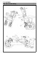
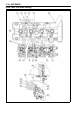
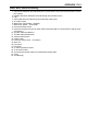
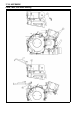
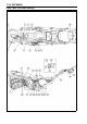
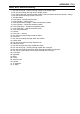
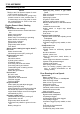
Cable, Wire, and Hose Routing
1. Cam sensor lead (Run the lead between the convex area of cap c enter and bolt head to secure
the coupler.)
2. Radiat
or fan switch lead (Run the lead through into the water hose.)
3. Cap
4. Catch cable (Run the cable through forward the water hose.)
5. Air su
ction valve
6. Water hose (Thermostat – Radiator)
7. Water hose (Head – Thermostat)
8. Inle
t air pressure sensor
9. Vacuum hose (Run the vacuum hose under the throttle cable to connect with t he inlet air pres-
sure sensor.)
10. Thro
ttle cables (accelerator)
11. Throttle cables (decelerator)
12. Vacuum balance tube
13. Cho
ke Cable
14. Hose (air suction valve – air cleaner)
15. Stick coil
16. Fue
l pump
17. Fuel hose
18. To inlet air pressure sensor
19
.
To
air suction valve
20. To prevent the throttle cable from unexpected coming down.
21. Cover
22
.
Th
rottle body