
Service Manual


ENGINE LU BRICATION SYSTEM 7-13
Oil Pump and Oil Line
•
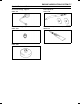
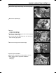
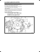
Install the inside oil pipe [A], separator [B], and the oil
return pipe [C] to the right crankcase [D].
○
Do not apply silicone sealant to the groove of the grommet
and the mating surface of the grommet [E].
○
Install the separator so that it’s smaller side [F] faces in-
side.
○
Apply a non-permanent locking agent to the oil pipe holder
bolt [G], oil return pipe clamp bolts [H] and oil pipe clamp
bolt [I].
○
If the oil nozzle [J] is removed, install it.
Tor q ue - Oil Pipe Holder Bolt: 11 N·m (1.1 kgf·m, 97 in·lb)
Oil Return P ipe Clamp Bolt: 11 N·m (1.1 kgf·m, 97
in·lb)
Oil Pipe Clamp Bolt: 11 N·m (1.1 kgf·m, 97 in·lb)
OilNozzle:2.9N·m(0.30kgf·m,26in·lb)
•
Install the removed parts.
Blowby Gas System Inspection
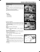
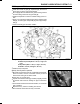
•
Be certain that all the hoses are routed without being flat-
tened or kinked, and are connected correctly to the oil
reserve tank and right air cleaner base.
If they are not, correct them.
•
Inspect the breather hoses [A], breather pipe [B], and the
air cleaner drain hose for damage or signs of deteriora-
tion.
○
These hoses should not be hard and brittle, nor should be
soft or swollen.
Replace it if any cracks or swelling are noticed.
•
Check that the hoses are securely connected.