
Service Manual

3-24 FU EL SYSTEM (DFI)
Troubleshooting the DFI System
○
There are two ways to inspect the DFI system. One is
Voltage Check Method and the other is Resistance Check
Method.
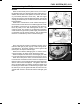
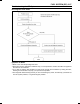
Voltage Check Method
○
This method is conducted by measuring the input voltage
[B] to a sensor [A] first, and then the output voltage [C]
from the sensor.
○
Sometime this method can detect a fault of the ECU.
○
Refer to each Sensor Inspection section for detail in this
chapter.
•
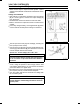
Use a fully charged battery, and a digital meter [D] which
can be read two decimal places voltage or resistance.
○
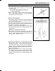
The DFI part connectors [A] have seals [B], including the
ECU (except for ISC valves).
•
Join the c onnector [A] and insert the needle adapter (spe-
cial tool) [C] inside the seal [B] from behind the connector
until the adapter reaches the terminal.
Special Tool - Needle Adapter Set: 57001–1457
CAUTION
Insert the needle adapter straight along the terminal
in the connector to prevent short-circuit between
terminals.
•
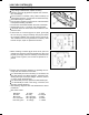
Make sure that measuring points are correct i n the con-
nector, noting the position of the lock [D] and the lead
color before measurement. Do not reverse connections
of the hand tester or a digital m eter.
•
Be careful not to short-circuit the leads of the DFI or elec-
trical system parts by contact between adapters.
•
Turn the ignition SW ON and measure the voltage with
the connector joined.
CAUTION
Incorrect, reverse connection or short circuit by
needle adapters could damage the DFI or electrical
system parts.