
User's Manual


ELECTRICAL SYSTEM 16-31
Charging System
•
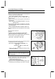
Install t he starter gear [A].
•
Again, clean the crankshaft tapered portion [B] and dry
there.
•
Fit the woodruff k ey [C] securely in the slot in the crank-
shaft before installing the alternator rotor.
•
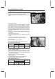
Install the alternator rotor [A] while turning [B] the starter
clutch gear [C].
•
Install the washer [A] s o that the chamfer side [B] faces
outward.
NOTE
○
Confirm the alternator rotor fit or not to the crankshaft
before tightening it with specified torque.
○
Install the rotor and tighten it with 70 N·m (7.0 kgf·m, 52
ft·lb) of torque.
○
Remove the washer and rotor bolt.
○
Check the tightening torque with rotor puller.
If the rotor is not pulled out with 20 N·m (2.0 kgf·m, 15
ft·lb) of drawing torque, it is installed correctly.
If the rotor is pulled out with under 20 N·m (2.0 kgf·m, 15
ft·lb) of drawing torque, clean off any oil dirt or flaw of the
crankshaft and rotor tapered portion, and dry them with
a clean cloth. Then, confirm that it is not pulled out with
above torque.
•
Tighten the alternator rotor bolt while holding the alterna-
tor rotor steady with the rotor holder.
Special Tool - Rotor Holder: 57001–1543
Torque - Alternator Rotor Bolt: 110 N·m (11 kgf·m, 81 ft·lb)