
User guide


“The Right Control for Your Application.” 12095 NW 39 Street, Coral Springs, FL 33065-2516
Telephone: 954-346-4900; Fax: 954-346-3377
KB Electronics, Inc. www.kbelectronics.com
Installation and Operation Manual Supplement
for Anti-Plug Reversing Module (APRM) (Part No. 9378)
FOR USE WITH MODEL KBPC-240D
(A42048) – Rev. A00 – 5/4/2010 Page 1 of 2
This supplement is for the APRM Installation and Operation Manual Rev. B (Part No. A40265).
The manual must be read and understood before installing and operating the drive.
For further assistance, contact our Sales Department at 954-346-4900 or Toll Free at 800-221-6570 (outside Florida).
DESCRIPTION OF CHANGES AFFECTING THE MANUAL
(The Parts List and Schematic (Table 4 and Figure 6, on pages 7 and 8) no longer apply to the SMT APRM and should not be used.)
TABLE 2 – GENERAL PERFORMANCE SPECIFICATIONS
Updated to show the correct Operating Temperature Range and Braking Time.
Replaces Table 2, on page 2 of the manual.
Parameter Specification
AC Line Input (50/60 Hz) (Jumper Selectable) (Volts AC) 115 or 208/230
Maximum Run/Brake or Forward/Reverse Operations per Minute* 4
Ambient Temperature Range (°C / °F) 0 – 40 / 32 – 104
*Based on a one (1) second braking time.
TABLE 3 – INTERCONNECTING WIRE HARNESS
Replaces Table 3, on page 5 of the manual.
Wire Color Location on Drive Wire Termination
Red A1A
Orange A1B
Black A2A
White A2B
Gray I1
White / Black I2
Quick-Connect Terminals
Yellow CON2
Brown* CON2
2-Pin Connector
*The brown wire has been added to CON2.
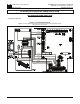
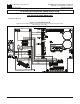
FIGURE 2 – REMOVAL OF DRIVE JUMPERS
Updated to show CON2.
Replaces Figure 2, on page 4 of the manual.
Continued on other side…