
User Manual

“The Right Control for Your Application.”
12095 NW 39 Street, Coral Springs, FL 33065-2516
Telephone: 954-346-4900; Fax: 954-346-3377
KB Electronics, Inc. www.KBelectronics.com
Dynamic Brake Module (Part No. 9598) Installation Instructions
Dynamic Brake Module (Part No. 9598) Installation InstructionsDynamic Brake Module (Part No. 9598) Installation Instructions
Dynamic Brake Module (Part No. 9598) Installation Instructions
(A40148) – Rev. B – 7/18/2006 – Z4181B00 Page 1 of 4
Dynamic Brake Module (Part No. 9598) Is Designed for Use with
Dynamic Brake Module (Part No. 9598) Is Designed for Use withDynamic Brake Module (Part No. 9598) Is Designed for Use with
Dynamic Brake Module (Part No. 9598) Is Designed for Use with
KBVF Series Drives: Model Nos. KBVF-21D, 22D, 13, 23, 23D, 14, 24, 24D
KBBL Series Drives: Model Nos. KBBL-2P2D, 2P3D, 2P6D, 21D, 22D, 23D, 24D
SAFETY WARNING! Please read carefully before proceeding.
This product should be installed and serviced by a qualified technician, electrician, or electrical maintenance person familiar with its
operation and the hazards involved. Proper installation, which includes wiring, mounting in proper enclosure, fusing or other current
protection, and grounding can reduce the chance of electrical shocks, fires, or explosion in this product or products used with this product,
such as electric motors, switches, coils, solenoids, and/or relays. Eye protection must be worn and insulated adjustment tools must be
used when working with drive under power. This product is constructed of materials (plastics, metals, carbon, silicon, etc.) which may be a
potential hazard. Proper shielding, grounding, and filtering of this product can reduce the emission of radio frequency interference (RFI)
which may adversely affect sensitive electronic equipment. If further information is required on this product, contact our Sales Department.
The drive contains electronic start/stop circuits which can be used to start and stop the drive. However, these circuits are never to be used
as safety disconnects since they are not fail-safe. Use only the AC line for this purpose.
Be sure to follow all instructions carefully. Fire and/or electrocution can result due to improper use of this product.
It is the responsibility of the equipment manufacturer and individual installer to supply this Safety Warning to the ultimate end user of this
product.
IMPORTANT
The KBVF Series Installation and Operation Manual (Part No. A40288) and the KBBL Series Installation Instructions (Part No. A40152) must
be read and understood before attempting to operate the Dynamic Brake Module.
Items Included in this Package
Dynamic Brake Module, Installation Instructions, Interconnect Wires, Jumper (for KBVF Series Drives only), Warranty Registration Card.
Dynamic Brake Module Rating
Up to 25% continuous braking torque and 200% instantaneous braking torque (maximum 1 HP (0.75 kW)).
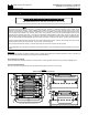
Figure 1
Mechanical Specifications (Inches/mm)
Recommended Mounting Screw (10 Places): #10
6.35
0.25
44.5
63.5
2.50
1.75
4.30
109
96.5
3.80
22.6
0.89
0.95
24.1
6.35
0.25
3.88
98.4
24.1
0.95
2.38
60.4
0.25
6.35