
User Manual

“The Right Control for Your Application.”
12095 NW 39 Street, Coral Springs, FL 33065-2516
Telephone: 954-346-4900; Fax: 954-346-3377
KB Electronics, Inc. www.KBelectronics.com
Dynamic Brake Module (Part No. 9598) Installation Instructions
Dynamic Brake Module (Part No. 9598) Installation InstructionsDynamic Brake Module (Part No. 9598) Installation Instructions
Dynamic Brake Module (Part No. 9598) Installation Instructions
(A40148) – Rev. B – 7/18/2006 – Z4181B00 Page 2 of 4
1
11
1 DESCRIPTION
DESCRIPTIONDESCRIPTION
DESCRIPTION
The Dynamic Brake Module (DBM) is designed to be used with the KBVF Series Drives (Model Nos. KBVF-21D, 22D, 13, 23, 23D, 14, 24,
24D) and the KBBL Series Drives (Model Nos. KBBL-2P2D, 2P3D, 2P6D, 21D, 22D, 23D, 24D). The DBM provides up to 25% continuous
braking torque and 200% instantaneous braking torque (maximum 1 HP (0.75 kW)).
2
22
2 MOUNTING INSTRUCTIONS
MOUNTING INSTRUCTIONSMOUNTING INSTRUCTIONS
MOUNTING INSTRUCTIONS
WARNING! This DBM must be mounted in an enclosure. Care should be taken to avoid extreme hazardous locations
where physical damage to the DBM can occur due to moisture, metal chips, dust, and other contamination, including corrosive
atmosphere that may be harmful. See Safety Warning, on page 1. Do not use this DBM in an explosion-proof application.
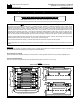
Application Note: The enclosure should be large enough to allow for proper heat dissipation (including additional cooling, if required) so
that the ambient temperature does not exceed 45 °C (113 °F). Leave enough room to allow for any wiring that is required. See Figure 1,
on page 1.
The DBM should be mounted close to the KBVF or KBBL Series Drive, as shown in Figure 2.
3
33
3 WIRING
WIRINGWIRING
WIRING
WARNING! Read Safety Warning, on page 1, before using the drive. Disconnect main power when making connections
to the drive. To avoid electric shock, be sure to properly ground the drive.
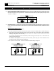
The DBM should be wired to the KBVF or KBBL Series Drive using the 9” 18AWG red/black Interconnect Wires which are provided.
Terminal “B+” on the DBM connects to Terminal “B+” on the KBVF or KBBL Series Drive. Terminal “B-“ on the DBM connects to Terminal
“B-“ on the KBVF or KBBL Series Drive. See Figure 2.
Figure 2
Connection Diagram
Drive*Dynamic Brake Module
*Layout, trimpot settings, and jumper settings may vary slightly.