MODEL KBAC-29 (1P) SUPPLEMENT IMPORTANT: The KBAC Series Installation and Operation Manual (Part No. A40206) must be read and understood before attempting to operate this drive. For further assistance, contact our sales Department at 954-346-4900 or Toll Free at 800-221-6570 (outside Florida). DESCRIPTION: Model KBAC-29 (1P) has been added to the KBDA Series of drives. This model is designed to accept single-phase 208/230 Volts AC line input only.
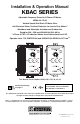
Installation & Operation Manual KBAC SERIES Adjustable Frequency Drives for 3-Phase AC Motors NEMA-4X / IP-65 Variable Speed / Soft-Start AC Motor Drive with Electronic Motor Overload Protection for Inverter Duty Motors1 Washdown and Watertight for Indoor and Outdoor Use Rated for 208 – 230 and 400/460 Volt 50 & 60 Hz 3-Phase & PSC 2 AC Induction Motors from Subfractional thru 5 HP Operates from 115, 208/230 Volt and 400/460 Volt 50/60 Hz AC Line 2,3 This Manual Covers Models KBAC-24D, 27D, 29, 45, 48 S
TABLE OF CONTENTS Section Page 1 Quick-Start Instructions . . . . . . . . . . . . . . . . . . . . . . . . . . . . . . . . . . . . . . . . . . . . . . . . . . . . . . . . . . . . . . . . 4 2 Safety Warning . . . . . . . . . . . . . . . . . . . . . . . . . . . . . . . . . . . . . . . . . . . . . . . . . . . . . . . . . . . . . . . . . . . . . . 5 3 Introduction . . . . . . . . . . . . . . . . . . . . . . . . . . . . . . . . . . . . . . . . . . . . . . . . . . . . . . . . . . . . . . . . . . . . . . . . .
30 31 32 33 34 35 36 37 38 39 40 Minimum Speed Trimpot (MIN) Range . . . . . . . . . . . . . . . . . . . . . . . . . . . . . . . . . . . . . . . . . . . . . . . . . . . . Maximum Speed Trimpot (MAX) Range . . . . . . . . . . . . . . . . . . . . . . . . . . . . . . . . . . . . . . . . . . . . . . . . . . . Acceleration Trimpot (ACCEL) Range . . . . . . . . . . . . . . . . . . . . . . . . . . . . . . . . . . . . . . . . . . . . . . . . . . . . . Deceleration Trimpot (DECEL) Range . . . . . . . . . . . . . .
1 QUICK-START INSTRUCTIONS Important – You must read these simplified instructions before proceeding. These instructions are to be used as a reference only and are not intended to replace the details provided herein. You must read the Safety Warning on, page 5, before proceeding. See Figure 1. Also see Section 4 - Important Application Information, on page 12. WARNING! Disconnect main power before making connections to the drive.
Models KBAC-45, 48: Designed to accept 3-phase (Terminals “L1”, “L2”, “L3”) AC line input only. Rated for 400/460 Volt AC line input only. See Figure 8, on page 14. 2 1.2 AC LINE FUSING – It is recommended that a fuse(s) or circuit breaker be installed in the AC line. Fuse each conductor that is not at ground potential. For the recommended fuse size, see Table 4, on page 10. Also see Section 10, on page 21. 1.
This product complies with all CE directives pertinent at the time of manufacture. Contact our Sales Department for Declaration of Conformity. Installation of a CE approved RFI filter is required. See RFI Filters & Chokes Selection Guide D-321 (Part No. A42027) for selection of filters to meet the Industrial or Residential Standard. Additional shielded cable and/or AC line cables may be required along with a signal isolator (SIAC (Part No. 9600)).
• Start/Stop Switch – Provides electronic start and stop functions. • Barrier Terminal Block – Facilitates wiring of motor, AC line, and Run/Fault Relay Output Contacts. • Jumper Selection of Drive Output Frequency – Increases the motor speed up to two times the rated RPM. • Ride-Through – Provides smooth recovery to the previous set speed during a momentary power loss (of less than 2 seconds). • Holding Torque at Zero Speed – Resists motor shaft rotation when the drive is in Stop Mode.
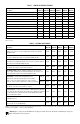
TABLE 1 – JUMPER SELECTABLE FEATURES Description1 PC Board Designation KBAC-24D KBAC-27D KBAC-29 KBAC-45 AC Line Input Voltage (115, 230) J1 3 3 — — KBAC-48 — Motor Horsepower (see Table 4 - Electrical Ratings, on page 10) J2 3 3 3 3 3 Automatic Ride-Through or Manual Restart (A*, M) J3 3 3 3 3 3 Frequency Multiplier (1X, 2X) J4 3 3 3 3 3 Motor Frequency (50Hz, 60Hz) J5 3 3 3 3 3 Fixed or Adjustable Boost (FIX, ADJ) J6 3 3 3 3 3 Regenerative or DC Injection Brak
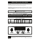
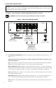
9 STATUS TB2 P2 P1 JOG MAX J11: I2 t Overload selection. See Section 6.10, on page 18. CON1: Used to connect optional accessories to the drive. See Table 2, on page 8. P3 MIN ACCEL BOOST CL A B C D E JOG COMP J9: Normally Open or Closed Stop Contact selection. See Section 6.8, on page 18. J10: Constant or Variable Torque selection. See Section 6.9, on page 18. DECEL JOG Terminal. Used with optional Run-Stop-Jog Switch Kit. See Table 2, on page 8. Adjustable Trimpots 2.
TABLE 3 – GENERAL PERFORMANCE SPECIFICATIONS Description Specification Factory Setting 115 Volt AC Line Input Voltage Operating Range (Volts AC) 115 (±15%) — 208/230 Volt AC Line Input Voltage Operating Range (Volts AC) 208 (-15%) / 230 (+15%) — 400/460 Volt AC Line Input Voltage Operating Range (Volts AC) 380 (-15%) – 460 (+15%) — Maximum Load (% Current Overload for 2 Minutes) 150 — Carrier, Switching Frequency (kHz) 16, 8 — Signal Following Input Voltage Range1 (Volts DC) 0–5 — Outpu
8.85 225 2.53 64.4 3* 1* 8.20 208 9.53 242 Maximum Depth: 5.86 149 Contains 2 mounting holes for standard 1/2” liquidtight fittings 2* 4* 2X ∅ 0.25 6.4 * Tighten these screws, in the sequence shown, to 12 in-lbs (14 kg-cm). 0.31 7.97 5.51 140 5.06 129 FIGURE 3 – MODEL KBAC-24D MECHANICAL SPECIFICATIONS (INCHES/mm) 11 0.25 6.4 7.55 192 7.15 181 2X 1.00 25.4 3.05 77.7 3* 1* 2X 8.50 216 2X 9.25 235 Maximum Depth: 0.30 7.37 7.25 184 9.
4 IMPORTANT APPLICATION INFORMATION 4.1 MOTOR WITH EXTERNAL FAN COOLING – Most totally enclosed fan-cooled (TEFC) and open ventilated 3-phase AC induction motors will overheat if used beyond a limited speed range at full torque. Therefore, it is necessary to reduce motor load as speed is decreased. Note: Some fan-cooled motors can be used over a wider speed range. Consult the motor manufacturer for details.
5 WIRING INSTRUCTIONS WARNING! Read Safety Warning, on page 5, before using the drive. Disconnect main power before making connections to the drive. To avoid electric shock, be sure to properly ground the drive. It is highly recommended that the SIAC Signal Isolator (Part No. 9600) be installed when using signal following. WARNING! Remote connections of potentiometer, switches, etc., will have wiring that is at line potential. It is required that the signal isolator be installed for remote connections.
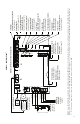
FIGURE 8 – MODELS KBAC-29*, 45, 48 AC LINE INPUT, MOTOR, AND GROUND CONNECTIONS Model KBAC-29 Only Wire the single-phase AC line input to Terminals "L1", "L2", as shown below. TB1 U V MOTOR Motor W L1 L2 L3 L1 AC LINE 208/230, 400/460 Volt 3-Phase, 50/60 Hz AC Line Input L2 L3 AC LINE Ground (Earth) 208/230 Volt Single-Phase, 50/60 Hz AC Line Input Ground (Earth) *Model KBAC-29 is rated 2 HP maximum with single-phase AC line input and 3 HP maximum with 3-phase AC line input.
inside the drive. The switch assembly may be removed if a liquidtight seal is used to cover the hole in the front cover. After applying power to the drive, momentarily set the Start/Stop switch to the “START” position.
The Enable function is established by wiring a switch or contact in series with the orange Main Speed Potentiometer lead which connects to Terminal “P2”. When the Enable Switch is closed, the motor will accelerate to the Main Speed Potentiometer setting. When the Enable Switch is opened, the motor will decelerate to stop.
Using pliers, gently rock the female terminal back and forth while pulling it upward. See Figure 17 6.2 6.3 FIGURE 17 – REMOVING JUMPER J1 ON MODELS KBAC-24D, 27D Terminal Removed MOTOR HORSEPOWER SELECTION (J2) – Set Jumper J2 to the corresponding position for the motor being used. See Figure 18. Terminal Installed AUTOMATIC RIDE-THROUGH OR MANUAL START SELECTION (J3)* – Jumper J3 is factory set to the “A” position for Automatic Ride-Through.
100/120 FIGURE 22 120 HZ & 100 HZ DRIVE OUTPUT FREQUENCY SELECTION J5 2X 50Hz 60Hz 1X 100 Hz Output with 50 Hz Motor (J4 Installed in “2X” Position) (J5 Installed in “50Hz” Position) J4 J5 50Hz 60Hz 120 Hz Output with 60 Hz Motor (J4 Installed in “2X” Position) (J5 Installed in “60Hz” Position) FIGURE 23 – FIXED OR ADJUSTABLE BOOST SELECTION Adjustable Boost (J6 Installed in “ADJ” Position) FIX Fixed Boost (Factory Setting) (J6 Installed in “FIX” Position) ADJ FIGURE 24 – REGENERATIVE OR DC IN
“Fault” Output Relay Operation (J8 Installed in “F” Position) F J8 R “Run” Output Relay Operation (Factory Setting) (J8 Installed in “R” Position) FIGURE 26 – NORMALLY OPEN OR CLOSED STOP CONTACT SELECTION Normally Closed Stop Contact (J9 Installed in “NC” Position) NO VT VT J10 CT Variable Torque (J10 Installed in “VT” Position) CT Constant Torque (Factory Setting) (J10 Installed in “CT” Position) FIGURE 28 – I 2 t OVERLOAD SELECTION 8.
20 RESET H. V.
9 DRIVE OPERATION 9.1 START-UP PROCEDURE – After the drive has been properly setup (jumpers and trimpots set to the desired positions) and wiring completed, the start-up procedure can begin. If the AC power has been properly brought to the drive, the power (PWR) LED will illuminate green. The status (ST) LED will indicate drive status, as described in Section 11.2. To start the drive, momentarily set the Start/Stop Switch to the “START” position. The motor will begin to accelerate to the set speed.
the user that all drive and microcontroller operating parameters are normal. Table 7, summarizes the “ST” LED functions.
12.4 DECELERATION (DECEL) – Sets the amount of time for the motor to decelerate from full speed to zero speed. The DECEL Trimpot is factory set to 1.5 seconds. For longer deceleration time, rotate the DECEL Trimpot clockwise. For more rapid deceleration, rotate the DECEL Trimpot counterclockwise. See Figure 33. FIGURE 33 – DECELERATION TRIMPOT RANGE 10 3 17 1.5 Application Note – On applications with high inertial loads, the 0.3 20 deceleration may automatically increase in time.
12.7 MOTOR OVERLOAD (I 2 t) WITH RMS CURRENT LIMIT (CL)* – Sets the current limit (overload), which limits the maximum current to the motor, which prevents motor burnout and eliminates nuisance trips. The CL Trimpot is factory set to 160% of the drive rated current. To increase the current limit, rotate the CL Trimpot clockwise. To decrease the current limit, rotate the CL Trimpot counterclockwise. See Figure 36, on page 23, and Figure 37. *UL approved as an electronic overload protector for motors.
WARNING! To avoid motor winding overheating and failure, do not overboost the motor. FIGURE 38 – BOOST TRIMPOT RANGE Note: An unloaded motor with excessive boost will draw more current than a partially loaded motor. 8 15 22 5 The boost voltage may be adjusted as follows: 0 30 1. Wire an AC RMS ammeter in series with one motor phase. 2. Run the motor unloaded at approximately 4 Hz (or 120 RPM). 3. Increase the boost until the ammeter reaches the motor nameplate rated current (Amps AC). 4.
– NOTES – 26
– NOTES – 27
LIMITED WARRANTY For a period of 18 months from the date of original purchase, KB Electronics, Inc. will repair or replace without charge, devices which our examination proves to be defective in material or workmanship. This warranty is valid if the unit has not been tampered with by unauthorized persons, misused, abused, or improperly installed and has been used in accordance with the instructions and/or ratings supplied. The foregoing is in lieu of any other warranty or guarantee, expressed or implied.