
Manual

SAFETY WARNING! Please read carefully before proceeding.
This product should be installed and serviced by a qualified technician, electrician, or electrical maintenance person familiar with its operation and the
hazards involved. Proper installation, which includes wiring, mounting in proper enclosure, fusing or other overcurrent protection, and grounding can
reduce the chance of electrical shocks, fires, or explosion in this product or products used with this product, such as electric motors, switches, coils,
solenoids, and/or relays. Eye protection must be worn and insulated adjustment tools must be used when working with control under power. This
product is constructed of materials (plastics, metals, carbon, silicon, etc.) which may be a potential hazard. Proper shielding, grounding and filtering
of this product can reduce the emission of radio frequency interference (RFI) which may adversely affect sensitive electronic equipment. If further infor-
mation is required on this product, contact the Sales Department.
This control contains electronic Start/Stop circuits that can be used to start and stop the control. However, these circuits are never to be used as
safety disconnects since they are not fail-safe. Use only the AC line for this purpose.
Be sure to follow all instructions carefully. Fire and/or electrocution can result due to improper use of this product.
It is the responsibility of the equipment manufacturer and individual installer to supply this Safety Warning to the ultimate end user of this product.
INSTALLATION INSTRUCTIONS
POWER ON/OFF SWITCH Part No. 9523 for Model KBAC-27D Inverter
DESCRIPTION
The Power On/Off Switch assembly is designed to provide a positive AC line power
disconnect. It can be installed in lieu of, or in addition to, the factory installed
Start/Stop Switch assembly. The switch is double pole which is used to disconnect
both AC lines. If only one AC line is to be disconnected, a single pole can be used.
Refer to local electrical codes that apply. The Power On/Off Switch assembly con-
tains two (2) blue and two (2) white wires which are terminated with 0.250” female
quick-connect terminals.
MOUNTING
WARNING! Make sure that the AC line is disconnected before
installing the Power On/Off Switch assembly.
1. Remove the rubber hole plug assembly that covers the POWER
position by unscrewing the retainer nut that is located on the
inside of the front cover.
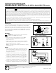
2. Align the switch key in the front cover and mount the Power On/Off
Switch assembly using the rubber boot that is provided. Do not over
tighten the rubber boot hex nut. See Figure 1.
Note: The switch bushing should protrude approximately 0.15” (3.8mm)
through the front cover.
WIRING
1. Remove the jumper assemblies that are installed on the L1A & L1B
and L2A & L2B terminals of the KBAC PC board. Using pliers, gen-
tly rock the female terminals back and forth vertically while pulling
them upward. See Figure 2.
2. Install the blue wire from the bottom of the Power On/Off Switch
assembly to the L1A terminal of the KBAC PC board. See Figure 3.
3. Install the other blue wire from the top of the Power On/Off Switch
assembly to the L1B terminal of the KBAC PC board. See Figure 3.
4. Install the white wire from the bottom of the Power On/Off Switch
assembly to the L2A terminal of the KBAC PC board. See Figure 3.
5. Install the other white wire form the top of the Power On/Off Switch
assembly to the L2B terminal of the KBAC PC board. See Figure 3.
!
KB ELECTRONICS, INC.
12095 NW 39th Street, Coral Springs, FL 33065-2516 • (954) 346-4900 • Fax (954) 346-3377
Outside Florida Call Toll Free (800) 221-6570 • E-mail – info@kbelectronics.com
www.kbelectronics.com
(A42127) – Rev. B – 6/2003
RUBBER BOOT
FRONT COVER
SWITCH BUSHING
HEX NUT
NYLON SPACER
SWITCH BODY
FIGURE 1 – MOUNTING THE POWER ON/OFF SWITCH
L2 AC LINE
L2A
L2B
L1A
L1B
ASSEMBLIES
JUMPER
REMOVED
INSTALLED
TERMINAL
TERMINAL
TO BE REMOVED
FIGURE 2 – JUMPER ASSEMBLIES
!
POWER ON/OFF SWITCH
BLUE
WHITE
WHITE
BLUE
PC BOARD
(BLK)
BC-
J1A
BC+
(RED)
B-
L1B
L2B
L2A
J1C
115V
J1B
L1A
230V
BCO
(WHT)
B+
FIGURE 3 – CONNECTION DIAGRAM