MODEL KBDA-29 (1P) SUPPLEMENT IMPORTANT: The KBDA Series Installation and Operation Manual (Part No. A40402) must be read and understood before attempting to operate this drive. For further assistance, contact our sales Department at 954-346-4900 or Toll Free at 800-221-6570 (outside Florida). DESCRIPTION: Model KBDA-29 (1P) has been added to the KBDA Series of drives. This model is designed to accept single-phase 208/230 Volts AC line input only.
Installation & Operation Manual KBDA SERIES ADJUSTABLE FREQUENCY DRIVES FOR 3-PHASE AC MOTORS NEMA-4X / IP-65 Washdown and Watertight for Indoor and Outdoor Use MULTI-FUNCTION KEYPAD WITH 4-DIGIT LED DISPLAY • Simplified Group Programming • 8 LED Status Indicators Rated for 208 – 230 and 400/460 Volt 50* & 60 Hz 3-Phase AC Induction Motors from Subfractional thru 5 HP Operates from 115, 208/230, and 400/460 Volt 50/60 Hz AC Line1 This Manual Covers Models KBDA-24D, 27D, 29, 45, 48 See Safety Warning,
TABLE OF CONTENTS Section Page 1 Quick-Start Instructions . . . . . . . . . . . . . . . . . . . . . . . . . . . . . . . . . . . . . . . . . . . . . . . . . . . . . . . . . . . . . . . 4 2 Safety Warning . . . . . . . . . . . . . . . . . . . . . . . . . . . . . . . . . . . . . . . . . . . . . . . . . . . . . . . . . . . . . . . . . . . . . . 6 3 Introduction . . . . . . . . . . . . . . . . . . . . . . . . . . . . . . . . . . . . . . . . . . . . . . . . . . . . . . . . . . . . . . . . . . . . . . . . .
20 21 22 23 24 25 26 27 28 29 30 31 32 33 34 35 36 37 38 39 Flow Chart to Program the Drive to Display Motor RPM . . . . . . . . . . . . . . . . . . . . . . . . . . . . . . . . . . . . . 27 Flow Chart to Program the Drive to Display Custom Units “012.0” . . . . . . . . . . . . . . . . . . . . . . . . . . . . 28 Flow Chart Showing Motor Current, Motor Voltage, and Bus Voltage added to the Basic Display . . . . 29 Function No. Description . . . . . . . . . . . . . . . . . . . . . . . . . . . . . . . . . . .
IMPORTANT APPLICATION INFORMATION 1. 50 Hz Motors – This drive has been factory programmed to operate 60 Hz motors. For 50 Hz motor operation, set Function No. 0.00 to “0001”. See Figure 16, on page 23. 2. Motor Current Setting – The motor current for all drive models is factory set to the maximum drive rating, as shown in Table 3, on page 10. In order for the motor overload protection to operate properly, the drive must be reprogrammed to the actual motor nameplate current. Use Function No. 0.
1.1 AC LINE INPUT CONNECTION – Connect the AC line input to Terminal Block TB1. See Section 6.1, on page 18. Application Note – If operation with a Ground-Fault Circuit-Interrupter (GFCI) is required, see Function No. 0.04, on page 32. Note: The rated AC line voltage of the drive must match the actual AC line input voltage. On Models KBDA-24D, 27D, the setting of Jumper J1 must match the AC line input voltage. Model KBDA-24D – Terminals “L1”, “L2” – Designed for single-phase AC line input only.
2 SAFETY WARNING Definition of Safety Warning Symbols Electrical Hazard Warning Symbol – Failure to observe this warning could result in electrical shock or electrocution. Operational Hazard Warning Symbol – Failure to observe this warning could result in serious injury or death. This product should be installed and serviced by a qualified technician, electrician, or electrical maintenance person familiar with its operation and the hazards involved.
3 INTRODUCTION Thank you for purchasing the KBDA Adjustable Frequency Drive. KB Electronics, Inc. is committed to providing total customer satisfaction by producing quality products that are easy to install and operate. The KBDA Adjustable Frequency Drives are variable speed controls housed in a rugged NEMA-4X / IP-65 washdown and watertight die-cast aluminum enclosure. They are designed to operate 208 – 230 and 400/460 Volt 50 & 60 Hz 3-phase AC induction motors from subfractional thru 5 HP.
• LED Status Indicators – The LEDs provide indication of the drive’s status and operating mode (Hz, PGM, LCL/REM, STOP, FWD, REV, OL, JOG/REM). • Multi-Function Output Relay Contacts – Can be used to turn on or off equipment or to signal a warning if the drive is put into various modes of operation. (The optional IODA Input/Output Multi-Function Board contains 9 digital and analog inputs, 4 digital and analog outputs, and 2 additional relay outputs.
TABLE 1 – OPTIONAL ACCESSORIES Accessory Part No. Model Model Model Model Model KBDA-24D KBDA-27D KBDA-29 KBDA-45 KBDA-48 Description On/Off AC Line Switch – Disconnects the AC line. Mounts on the enclosure cover and is supplied with a switch seal to maintain liquidtight integrity.
TABLE 3 – ELECTRICAL RATINGS AC Line Input Output Fuse or Circuit Maximum Continuous Maximum Breaker Voltage Maximum Net Wt. Part No. Volts AC2 Phase Current Range Rating Load Current3 Horsepower (Gray / White 1) (50/60 Hz) (φ) (Amps AC) (Amps AC) (Volts AC) (RMS Amps/Phase) (HP (kW)) lbs kg Model KBDA-24D4 9536/9537 KBDA-27D4,5 9543/9544 KBDA-296,7 9545 /9546 115 1 16 20 208/230 1 10 15 115 1 22 208/230 1 15 1 3 208/230 0 – 230 3.6 1 (.75) 25 0 – 230 5.5 1 ⁄2 (1.
115V J1 230V TB2 CON1 NO COM NC FIGURE 3 – MODEL KBDA-24D DRIVE LAYOUT L1A L1B L2A L2B TB1 MOTOR U V W L1 L2 AC LINE 11
TB2 CON1 NO COM NC FIGURE 4 – MODEL KBDA-27D DRIVE LAYOUT J1 115V 230V L2B L1B L2A L1A TB1 U 12 V MOTOR W L2 L3 AC LINE
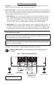
TB2 CON1 NO COM NC FIGURE 5 – MODELS KBDA-29, 45, 48 DRIVE LAYOUT L1B L1A L2B L2A L3B L3A TB1 U V MOTOR W L1 L2 AC LINE L3 13
FIGURE 6 – MODEL KBDA-24D MECHANICAL SPECIFICATIONS (Inches/mm) 5.51 140 5.06 129 0.31 7.97 2X ø 4* 0.275 7.0 Max. Depth: 5.86 149 2.53 64.4 1* 9.53 242 8.85 225 8.20 208 2* 3* Model KBDA-24D contains mounting holes for standard 1/2” liquidtight fittings. The recommended mounting screw size is 1/4” (M6). *Tighten the four enclosure cover screws, in the sequence shown, to 12 in-lbs (14 kg-cm).
FIGURE 7 – MODELS KBDA-27D, 29, 45, 48 MECHANICAL SPECIFICATIONS (Inches/mm) 4X ø 0.275 7.0 2X 4* 1.00 25.4 2X 0.30 7.37 1* 8.50 216 9.25 235 9.80 249 2* 3* 7.15 181 7.55 192 Max. Depth: 7.25 184 Models KBDA-27D, 29, 45, 48 contain two mounting holes for standard 1/2” liquidtight fittings and one mounting hole for standard 3/4” liquidtight fitting. The recommended mounting screw size is 1/4” (M6). *Tighten the four enclosure cover screws, in the sequence shown, to 12 in-lbs (14 kg-cm).
4 IMPORTANT APPLICATION INFORMATION 4.1 MOTOR WITH EXTERNAL FAN COOLING – Most totally enclosed fan-cooled (TEFC) and open ventilated 3-phase AC induction motors will overheat if used beyond a limited speed range at full torque. Therefore, it is necessary to reduce motor load as speed is decreased. Note: Some fan-cooled motors can be used over a wider speed range. Consult the motor manufacturer for details. FIGURE 8 – MAXIMUM ALLOWED MOTOR TORQUE VS.
If the motor is overloaded to 120% of the Motor Nameplate Rated Current setting, the I2t Timer starts. If the motor continues to be overloaded at the 120% level, the timer will shut down the drive after 30 minutes. If the motor is overloaded to 160% of full load, the drive will trip in 6 seconds. *UL approved as an overload protector for motors. 5 MOUNTING INSTRUCTIONS It is recommended that the drive be mounted vertically on a flat surface with adequate ventilation.
TABLE 4 – DRIVE TERMINAL BLOCK WIRE AND TIGHTENING TORQUE SPECIFICATIONS Maximum Wire Size (Cu) Recommended Tightening Torque Terminal Block Description Model AWG mm2 in-lbs TB1 AC Line Input and Motor Connections KBDA-24D 12 3.3 7 8 KBDA-27D, 29, 45, 48 12 3.3 12 14 TB2 Run/Fault Output Relay Contacts All 16 1.3 3.5 4 6.1 kg-cm AC LINE INPUT CONNECTION (see Warning, on page 17) – Connect the AC line input to Terminal Block TB1. See Electrical Ratings, Table 3, on page 10.
FIGURE 11 – MODELS KBDA-291, 452, 482 AC LINE INPUT, MOTOR, AND GROUND CONNECTIONS MOTOR Model KBDA-29 Only Wire the single-phase AC line input to Terminals "L1" & "L2", as shown below. AC LINE TB1 U Ground (Earth) V W L1 L2 L3 L1 208/230, 400/460 Volt 3-Phase, 50/60 Hz AC Line Input Motor L3 L2 208/230 Volt Single-Phase, 50/60 Hz AC Line Input Ground (Earth) Notes: 1. Model KBDA-29 is rated for 2 HP maximum with single-phase AC line input and 3 HP maximum with 3-phase AC line input. 2.
When the Multi-Function Output Relay is programmed to function as a “Fault” relay (Function No. 5.00 set to “0001”) and a fault occurs while the drive is in the Run Mode, the relay contacts will change state. The Normally Open (N.O.) contact (closed in the Run Mode) will open and the Normally Closed (N.C.) contact (open in the Run Mode) will close. See Table 5, on page 19.
8.2 The hi-pot tester must have an automatic ramp-up to the test voltage and an automatic rampdown to zero voltage. Note: If the hi-pot tester does not have automatic ramping, then the hi-pot output must be manually increased to the test voltage and then manually reduced to zero. This procedure must be followed for each machine to be tested. A suggested hi-pot tester is Slaughter Model 2550.
operational status, as described in Section 11, on page 41. A Main Speed Potentiometer is also provided to set the Drive Frequency (Function No. 2.00 set to “0001”). See Figure 2, on page 10. Note: To avoid damage, never operate the keypad with a screwdriver or other sharp-ended tool. TABLE 6 – KEYPAD DESCRIPTION Key Description Starts or Stops the drive Changes motor direction. Up Key: Increases Output Frequency, Set Frequency, Function Number Value, and Code setting.
FIGURE 16 – FLOW CHART TO PROGRAM THE DRIVE FOR 50 HZ MOTORS POWER ON Press Program Key to Display Function No. Group No. Digit Flashes ("PGM" LED On) Press Read Key to Read Code Rated Motor Frequency Code (60 Hz) Digit Flashes Press Up Key 1 Time to Increase Digit 50 Hz Rated Motor Frequency Code Digit Flashes Press Enter Key to Save New Code "End" Momentarily Displays which Confirms Programming Rated Motor Frequency Code No.
FIGURE 17 – FLOW CHART TO PROGRAM MOTOR CURRENT FROM 6.7 AMPS TO 5.5 AMPS POWER ON Set Frequency Flashes ("FWD", "STOP", "Hz" LEDs On) Press Program Key to Display Function No. Group No. Digit Flashes ("PGM" LED On) Press Shift Key 2 Times to Move Digit Code No. Digit Flashes Press Up Key 1 Time to Increase Digit Motor Nameplate Current Code No.
FIGURE 18 – FLOW CHART TO CHANGE SET FREQUENCY FROM 5.00 Hz TO 43.
FIGURE 19 – FLOW CHART TO PROGRAM ACCEL TIME FROM 1.5 SECONDS TO 120 SECONDS POWER ON Set Frequency Flashes ("FWD", "STOP", "Hz" LEDs On) Press Program Key to Display Function No. Group No. Digit Flashes ("PGM" LED On) Press Up Key 3 Times to Increase Digit Group No. Digit Flashes Press Shift Key 2 Times to Move Digit Code No.
FIGURE 20 – FLOW CHART TO PROGRAM THE DRIVE TO DISPLAY MOTOR RPM POWER ON Set Frequency Flashes ("FWD", "STOP", "Hz" LEDs On) Press Program Key to Display Function No. Group No. Digit Flashes ("PGM" LED On) Press Up Key 4 Times to Increase Digit Display Mode Function No.
FIGURE 21 – FLOW CHART TO PROGRAM THE DRIVE TO DISPLAY CUSTOM UNITS “012.0” POWER ON Set Frequency Flashes ("FWD", "STOP", "Hz" LEDs On) Press Program Key to Display Function No. Group No. Digit Flashes ("PGM" LED On) Press Up Key 4 Times to Increase Digit Display Mode Function No.
FIGURE 22 – FLOW CHART SHOWING MOTOR CURRENT, MOTOR VOLTAGE, AND BUS VOLTAGE ADDED TO THE BASIC DISPLAY* POWER ON Set Frequency Flashes ("FWD", "STOP", "Hz" LEDs On) Press Run Key to Run Drive Set Frequency ("STOP" LED Off) Press Display Key to Change Display Group No Digit Flashes ("PGM" LED On) Press Display Key to Change Display Motor Current ("PGM" LED Off) Press Display Key to Change Display Motor Voltage Press Display Key to Change Display Bus Voltage Press Display Key to Change Display
9.4 4-DIGIT DISPLAY – The 4-digit display provides readout of drive status, operating parameters, and faults. See Table 7 for the Digital Readout Codes displayed and their descriptions. WARNING! Do not depend on the LEDs or the 4-Digit Display to no longer be illuminated as a guaranteed power off condition. Be sure the main power switch or circuit breaker is in the “OFF” position before servicing the drive.
9.5 FAULT RECOVERY – The drive monitors many faults. See Function No. 1.05, on page 33, for restarting the drive after a fault has been cleared. See Section 9.4, on page 30, for the Digital Readout Codes. See Section 11, on page 41, for descriptions of the Diagnostic LEDs. See Appendix A, on page 42, for IODA faults.
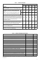
KBDA PROGRAMMABLE FUNCTION SUMMARY LIST (REV. 100.1) PROGRAMMABLE FUNCTION GROUPS Function Group No.
FUNCTION GROUP 1 – RUN/STOP MODE Function No. Description Range/Code Factory Setting 1.00* Run/Stop-Forward/Reverse Control 0000: Keypad 0001: External Contacts(1) 0002: Communication(2) 0000 1.01* Forward/Reverse Control 0000: Instant Reverse 0001: Stop Command Must be Given Prior to Reverse Command 0002: Reverse Command Disabled 0003: Forward Command Disabled 0000 1.02* Motor Direction 0000: Forward 0001: Reverse 0000 1.
FUNCTION GROUP 2 – FREQUENCY CONTROL Function No. Description Code Factory Setting 0000: Keypad 0001: Built-In Potentiometer 0002: Analog Signal 1(1) 0000 2.00* Frequency Control 2.
FUNCTION GROUP 4 – DIGITAL DISPLAY MODES Function No. Description 4.00 Display Mode 0000: Frequency 0001: RPM(1) 0002: Custom Units 0000 4.01 Custom Units Significant Digits 0 – 9999 100 4.02 Custom Units Display 0000: 0001: 0002: 0003: 0000 4.03 Display in Stop Mode 0000: Displays Last Run Setting 0001: Displays “StoP” 0002: Displays “0000” 0000 4.04 Motor Current Display(2), (3) 0000: Disabled 0001: Enabled 0000 4.
FUNCTION GROUP 6 – DRIVE STATUS AND RESET Function No. 6.00* 6.01* 6.02* 6.03* 6.04* 6.05** Description Software Version Drive Horsepower Fault Log 1 Fault Log 2 Fault Log 3 Reset Drive to Factory Setting Code — — — — — 1110: 50 Hz Operation 1111: 60 Hz Operation Factory Setting — — — — — 0000 * Read only. ** Functions which can only be changed while the drive is in the Stop Mode. FUNCTION GROUP 7 – MULTI-FUNCTION INPUT TERMINALS (IODA OPTION BOARD REQUIRED) Function No.
FUNCTION GROUP 8 – MULTI-FUNCTION OUTPUT RELAYS AND OUTPUT SIGNAL OPERATION (IODA OPTION BOARD REQUIRED) Function No. Description Range/Code 0000: Run 0001: Fault (1) 0002: Target Frequency (Function No. 8.04 ± Function No. 8.05) 0003: Frequency Threshold Level (> Function No. 8.04 – Function No. 8.05) (2) 0004: Frequency Threshold Level (< Function No. 8.04 + Function No. 8.05) (3) 0005: I2t or I•t Fault 0006: Load Loss (See Function No. 5.
FUNCTION GROUP 9 – ANALOG INPUT SIGNAL OPERATION (IODA OPTION BOARD REQUIRED) Function No. 9.00 Description Range/Code Analog Input 1 Gain (%)(1) 0 – 500 Factory Setting 100 9.01 Analog Input 1 Slope 0000: Positive 0001: Negative 9.02 Analog Input 1 Offset (%)(1) 0 – 100 9.03 Analog Input 1 Type(1) 0000: Unidirectional 0001: Bidirectional 0000 9.04 9.05 Analog Input 1 Response Time (mSec)(1) Analog Input 2 Gain (%)(2) 2 – 100 0 – 500 2 100 9.
FUNCTION GROUP 10 – COMMUNICATION MODE (DIAC OPTION BOARD REQUIRED) (Continued) Function No. 10.04 10.05 10.06 ** 10.07 ** 10.08 ** 10.09 ** 10.
FUNCTION GROUP 11 – RESERVED FUNCTIONS Function No. 11.00 – 11.09 Description Reserved Range/Code — Factory Setting — TABLE 8 – MODEL SOFTWARE REVISION CODES (REV. 100.1) The Programmable Function List, on Pages 32 – 40, is Applicable to the Following* Software Revision Codes * Or higher. 40 Model No. Software Revision Code KBDA-24D KBDA-27D KBDA-29 KBDA-45 KBDA-48 29 / 1.02 35 / 1.02 37 / 1.01 38 / 1.01 39 / 1.
11 DIAGNOSTIC LEDs The drive contains 8 Status LEDs to provide indication of the drive’s status and operating mode (Hz, PGM, LCL/REM, STOP, FWD, REV, OL, JOG/REM). See Table 9, for a description of the LEDs. WARNING! Do not depend on the LEDs or the 4-Digit Display to no longer be illuminated as a guaranteed power off condition. Be sure the main power switch or circuit breaker is in the “OFF” position before servicing the drive. TABLE 9 – LED DESCRIPTIONS LED Description Illuminates when Jog is selected.
APPENDIX A – OPTIONAL IODA INPUT/OUTPUT MULTI-FUNCTION BOARD The IODA Input/Output Multi-Function Board provides a variety of functions, which include preset frequency, up/down frequency control, signal isolation, isolated output voltage for controlling auxiliary devices, open collector outputs, and output relay contacts. The IODA mounts on the drive’s PC board with 2 snapins (located on the bottom of the mounting base) and 2 screws (provided).
FIGURE 24 – IODA LAYOUT (ALL MODELS)* 8 23 9 24 10 25 11 IODA 26 12 27 13 28 14 Mounting Screw Holes for Large Base Large Base (Shaded Section) Mounting Screw Holes for Small Base 20 6 21 7 CUR VOLT VOLT CUR 5 CON2 19 CON2: Factory Use Only 22 J2 PWR 15 1 16 2 CON1 17 STATUS 3 18 4 J3 TB1 Terminal Block TB1 Two Snap-Ins to Secure IODA to Mounting Base MAX2 Trimpot: Signal Scaling for Analog Input 2 VOLT MAX1 MAX2 J1: Current or Voltage Signal Input Selection for An
TABLE 12 – IODA FUNCTIONS AND FEATURES Terminal Assignment Multi-Function Input Terminal Codes 0000: Preset Frequency Operation1 0001: Preset Frequency Operation1 0002: Preset Frequency Operation1 0003: Up Frequency Command (See Function No. 7.14) 0004: Down Frequency Command (See Function No. 7.14) 0005: Accel/Decel 2 (See Function No. 7.16) 0006: Forward/Stop Command 0007: Reverse/Stop Command 0008: External Fault 0009: Reset 0010: N.O. Start (2-Wire or 3-Wire Start/Stop) 0011: N.C.
PRESET FREQUENCIES The drive is factory programmed for 7 Preset Frequencies, which can be selected using remote switches or contacts connected to the Multi-Function Input Terminals “1” – “7”, as shown in Figure 26. See Table 13, for the Multi-Function Input Terminals to select for the preset frequencies. The Preset Frequencies can be changed from their factory settings by reprogramming Preset Frequencies 1 – 7 (Function Nos. 7.07 – 7.13).
FIGURE 27 – UP/DOWN FREQUENCY CONTROL SWITCH OR CONTACT CONNECTIONS AND FUNCTION SETTINGS Function Settings TB1 15 17 16 1 2 18 3 19 21 20 5 4 6 22 23 8 7 9 24 25 26 27 28 10 11 12 13 14 Up Down Function No. Range/Code 2.00 Frequency Control 0005 Up/Down Using MFITs 7.03 Multi-Function Input Terminal 4 0003 Up Frequency Command 7.04 Multi-Function Input Terminal 5 0004 Down Frequency Command 7.14 Up/Down Frequency Control Mode 0000 or 0001 Free-Running or Incremental 7.
FIGURE 29 – FORWARD/STOP-REVERSE/STOP SWITCH OR CONTACT CONNECTIONS AND FUNCTION SETTINGS Function Settings TB1 15 16 1 17 2 18 3 19 20 5 4 Forward/Stop A5. 21 6 22 7 23 8 9 24 25 26 27 28 10 11 12 13 14 Reverse/Stop Function No. Code 1.00 Run/Stop-Forward/Reverse Control 0001 External Contacts 7.03 Multi-Function Input Terminal 4 0006 Forward/Stop Command 7.
A7. 2-WIRE AND 3-WIRE START/STOP A remote Start/Stop Switch or Contact can be used to start and stop the motor in lieu of the RUN/STOP Key on the Keypad. The Start/Stop Switch or Contact can be connected for 2-Wire or 3Wire configuration, as described below. 2-WIRE START/STOP SWITCH OR CONTACT CONNECTION 2-Wire Start/Stop requires a maintained switch or contact. Connect the switch or contact to the respective Multi-Function Input Terminal “1” – “7” and to Terminal “8” (common), as shown on Figure 32.
FIGURE 33 – 3-WIRE START/STOP SWITCH OR CONTACT CONNECTION AND FUNCTION SETTINGS Function Settings TB1 15 16 1 17 2 18 3 Start Stop 19 4 20 21 6 5 22 23 8 7 9 24 25 26 27 28 10 11 12 13 14 Momentarily close the Start Switch or Contact to run the drive. Momentarily open the Stop Switch or Contact to stop the drive. Function No. Code 1.00 Run/Stop-Forward/Reverse Control 0001 External Contacts 7.00 Multi-Function Input Terminal 1 0010 Normally Open Start 7.
TABLE 14 – ANALOG INPUT 1 ELECTRICAL RATINGS Parameter Specification Factory setting Voltage Range (Volts DC) 0 – ±5 0–5 MAX1 Scaling Trimpot Range (Volts DC) 0 – 24 5 Analog Input 2 – Connect the signal input to Terminal “21” and the common to Terminal “22”, as shown in Figure 35. See settings for Analog Input 2 (Function Nos. 9.05 – 9.09). Set Frequency Control (Function No. 2.00) to Analog Input 2 (“0003”).
A9. ANALOG SIGNAL OUTPUT Two analog signal outputs are provided, which will linearly follow the parameter programmed in Analog Output 1 Mode (Function No. 8.06) and Analog Output 2 Mode (Function No 8.08). They can be used to monitor Motor Frequency, Set Frequency, Motor Voltage, Bus Voltage, and Motor Current. See Table 16, for the Analog Outputs 1 and 2 Electrical Ratings. Analog Output 1 – Connect the auxiliary device signal input to Terminal “15” and the common to Terminal “16”, as shown in Figure 36.
BIDIRECTIONAL MOTOR OPERATION (Use Analog Input 1 Only) Connect the potentiometer to Terminals “9” (+5 Volts), “19” (Analog Input 1), and “10” (-5 Volts), as shown in Figure 37. Set Frequency Control (Function No. 2.00) to Analog Input 1 (“0002”). In this mode, the remote potentiometer is set for zero speed at 50% rotation. Rotating the potentiometer clockwise will increase motor frequency in the forward direction.
Multi-Function Output Relay 2 Contacts Normally Open (N.O.) Contact: TB1 Terminal “26”. Common (COM): TB1 Terminal “27” (contact common for Relay 2 only). Normally Closed (N.C.) Contact: TB1 Terminal “28”. FIGURE 38 – MULTI-FUNCTION OUTPUT RELAY CONTACTS CONNECTIONS AND FUNCTION SETTINGS Function Settings Relay 1 Relay 2 Function No. Code 0000 – 0008 Run, Fault, Target Frequency, Frequency Threshold Level 8.00 (> 8.04 – 8.05), Multi-Function Frequency Threshold Level Output Relay 1 (< 8.04 + 8.
FIGURE 39 – MULTI-FUNCTION OPEN COLLECTOR CONNECTIONS AND FUNCTION SETTINGS Function Settings Function No. Output 1 Output 2 TB1 15 16 1 17 2 18 3 20 19 4 5 22 21 6 7 23 8 9 24 25 26 27 28 10 11 12 13 14 O.C. COM O.C. COM Output 1 Output 2 Code 0000 – 0008 Run, Fault, Target Frequency, Frequency Threshold Level 8.02 (> 8.04 – 8.05), Multi-Function Open Collector Frequency Threshold Level Output 1 (< 8.04 + 8.
– NOTES – 55
LIMITED WARRANTY For a period of 18 months from the date of original purchase, KB Electronics, Inc. will repair or replace without charge, devices which our examination proves to be defective in material or workmanship. This warranty is valid if the unit has not been tampered with by unauthorized persons, misused, abused, or improperly installed and has been used in accordance with the instructions and/or ratings supplied. The foregoing is in lieu of any other warranty or guarantee, expressed or implied.