
Instruction Manual


10
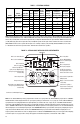
Notes: 1. White FDA approved finish. 2. Bold indicates factory setting of AC line input voltage for Models KBDA-24D, 27D. 3. Factory setting
of motor current (Function No. 0.01). 4. Models KBDA-24D, 27D contain an AC line input volta
ge selection jumper. 5. Model KBDA-27D is
rated 1
1
⁄2 HP (1.13 kW) with 115 Volt AC line input and 2 HP (1.5 kW) with 208/230 Volt AC line input. 6. Model KBDA-29 is rated 2 HP
(1.5 kW) with single-phase AC line input and 3 HP (2.25 kW) with 3-phase AC line input. 7. Also contain AC Line Phase Loss Detection
(Model KBDA-29: when used on 3-phase AC line input set for 7.0
Amps or higher (3 HP (2.25 kW)). 8. Models KBDA-45, 48 are rated
0
– 400 Volts AC for 50 Hz motor operation and 0 – 460 Volts AC for 60 Hz motor operation.
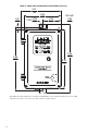
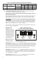
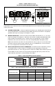
Notes: 1. The JOG-LCL/REM Key is factory programmed to function as a Jog Key. When the JOG-LCL/REM Key is pressed,
the
“JOG/REM”
LED will illuminate and the display will show the Jog Frequency Setting (see Function No. 3.13, on page 34). 2. If the JOG-LCL/REM Key is
reprogrammed for Local (Keypad) and Remote Signal Operation (see Function No. 2.02, on page 34),
the “LCL/REM” LED will illuminate.
Pressing the JOG-LCL/REM Key will toggle between Local (Keypad) and Remote Signal Operation. When Remote Signal Operation is select-
ed, the “JOG/REM” LED will flash. The optional IODA (Part No. 9668) is required for remote signal operation. 3. The “Hz” LED will illuminate
when the display is set to sho
w Output F
requency. 4. If the PROGRAM/DISPLAY Key is pressed while Set Frequency is displayed, the previ-
ously entered Function Number will be shown.
If the PROGRAM/DISPLAY Key is pressed while Function Number is displayed, the Set
Frequency will be shown. When more than one display function is enabled, the PROGRAM/DISPLAY Key is used to toggle between displays,
as shown in Figure 22, on page 29. 5. To change the Keypad for Potentiometer Operation, set Function No. 2.00 to “0001”.
TABLE 3 – ELECTRICAL RATINGS
Model
Part No.
(Gray / White
1
)
AC Line Input
Fuse or
Circuit
Breaker
Rating
(Amps AC)
Output
Net Wt.
Volts AC
2
(50/60 Hz)
Phase
(
φ)
Maximum
Current
(Amps AC)
Voltage
Range
(Volts AC)
Maximum
Continuous
Load Current
3
(RMS Amps/Phase)
Maximum
Horsepower
(HP (kW))
lbs kg
KBDA-24D
4
9536/9537
115 1 16 20
0 – 230 3.6 1 (.75) 5.9 2.7
208/230 1 10 15
KBDA-27D
4,5
9543/9544
115 1 22 25 0 – 230 5.5 1
1
⁄2 (1.13)
10.3 4.7
208/230 1 15 20 0 – 230
6.7
3
2 (1.5)
KBDA-29
6,7
9545 /9546 208/230
1 15 20 0 – 230 6.7 2 (1.5)
10.3 4.7
3 10.8 15 0 – 230
9.0
3
3 (2.25)
KBDA-45
7,8
9659/9660 400/460 3 5.3 10 0 – 400/460 4.6 3 (2.25) 10.3 4.7
KBDA-48
7,8
9661 /9662 400 /460 3 9.6 15 0 – 400/460 8.3 5 (3.75) 10.3 4.7
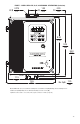
FIGURE 2 – KEYPAD LAYOUT WITH MAIN SPEED POTENTIOMETER
Down Key: Decreases Output Frequency,
Set Frequency, Function Number Value,
and Code setting.
Starts or Stops the drive.
Changes motor direction.
Up Key: Increases Output Frequency,
Set Frequency, Function Number Value,
and Code setting.
Drive is in Jog Operation
or Remote Signal Opera tion.
1, 2
Drive is in Overload.
Drive is set for Forward Direction.
Drive is set for Reverse Direction.
Displays or enters a Function Value
or Code Setting.
Used to enter the Program Mode
4
and Display Mode.
Sets the drive to Jog Mode or
changes between Local (Keypad)
or Remote Signal Opera tion.
1, 2
Left Shift / Reset Key: Moves
the changeable digit or Resets
the drive after a fault has cleared.
Drive Frequency displayed.
3
Drive is in Program Mode.
Drive is in Stop Mode.
Indicates JOG-LCL/REM Key
is set for Local/Remote Signal
Operation.
2
4-Digit Display
Potentiometer: Sets Drive Output Frequency.
5