
Instruction Manual

9 DRIVE OPERATION
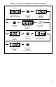
Before operating the drive, read Section 9.2, for instructions on the Digital Keypad Operation. See
Figure 2, on page 10, for the keypad layout.
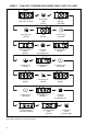
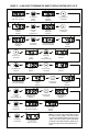
The 4-digit display can indicate various functions of the drive: Set Frequency, Motor RPM, Output
Current and Voltage, Custom Units, Function Numbers, Function Codes or Values, and Fault Codes.
See Section 9.4, on page 30.
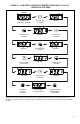
See Section 9.3, on pages 22 – 29, for information on programming the drive. If an error message
appears while pr
ogramming the drive, see Section 9.5, on page 31.
9.1
START-UP PROCEDURE – After the drive has been properly setup and all connections complet-
ed, the start-up procedur
e can begin. If the AC power has been properly brought to the drive, the
LEDs will indicate the drive’s status, as described in Section 11, on page 41. See Section 9.4, on
page 30, for the Digital Readout Codes.
To start the drive, press the RUN Key. The motor will begin to accelerate to the Set Frequency.
The factory set frequency is 05.00 Hz.
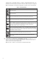
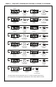
9.2 KEYPAD DESCRIPTION – The Keypad has eight (8) keys, which are used to program drive func-
tions, as described in Table 6, on page 22. The eight (8) LEDs pr
ovide indication of the drive’
s
21
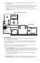
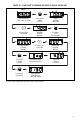
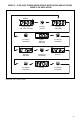
8.2 The hi-pot tester must have an automatic ramp-up to the test voltage and an automatic ramp-
down to zero voltage.
N
ote: If the hi-pot tester does not have automatic ramping, then the hi-pot output must be manu-
ally incr
eased to the test voltage and then manually r
educed to zero. This procedure must be fol-
lowed for each machine to be tested. A suggested hi-pot tester is Slaughter Model 2550.
CAUTION! Instantly applying the hi-pot voltage will cause irr
eversible damage to the drive, which
w
ill void the warranty.
FIGURE 15 – TYPICAL HI-POT TEST SETUP
ChassisChassis
Machine Equipment or Frame
Adjustable Frequency Drive
L2
(Main Power Disconnected)
to AC Line Inputs
Connect Hi-Pot
L2
L1
Auxiliary Equipment
L3
AC Line Input
H. V.
MAX
ZERO
L1
RESET
RETURN
10mA0mA
VOLTAGETEST
AC KILOVOLTS
LEAKAGE
1
0
3
2
High Voltage Dielectric Withstand Tester (Hi-Pot Tester)
V
Motor Wires
W
Frame
Connect All Drive Terminals Together
(Main Power Disconnected)
U