
Instruction Manual


51
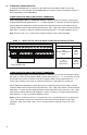
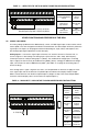
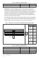
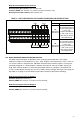
A10. REMOTE MAIN SPEED POTENTIOMETER
A remote Main Speed Potentiometer (5 kΩ) can be used in lieu of the Keypad or the Built-In
Potentiometer. The Main Speed Potentiometer can be connected for bidir
ectional, forward, or reverse
motor speed control, as described on page 52.
A9. ANALOG SIGNAL OUTPUT
Two analog signal outputs are pr
ovided, which will linearly follow the parameter programmed in
Analog Output 1 Mode (Function No. 8.06) and Analog Output 2 Mode (Function No 8.08). They can
be used to monitor Motor Frequency, Set Frequency, Motor Voltage, Bus Voltage, and Motor Current.
See Table 16, for the Analog Outputs 1 and 2 Electrical Ratings.
Analog Output 1 – Connect the auxiliary device signal input to Terminal “15” and the common to
T
erminal “16”, as shown in Figur
e 36. Set Analog Output 1 Mode (Function No. 8.06) for the desired
parameter to be monitored (factory set to Motor Frequency (“0000”)). Set Analog Output 1 Gain
(Function No. 8.07) for the desired signal gain (factory set to 100%). Analog Output 1 provides a 0 – 5
Volt DC signal output.
Analog Output 2 – Connect the auxiliary device signal input to Terminal “17” and the common to
T
erminal “18”, as shown in Figur
e 36. Set Analog Output 2 Mode (Function No. 8.08) for the desired
parameter to be monitored (factory set to Motor Frequency (“0000”)). Set Analog Output 2 Type
(Function No. 8.09) to ((“0000”) (factory setting)) for 0 – 5 Volt DC output. Set Analog Output 2 Type
(Function No. 8.09) to “0001” for 0 – 20 mA DC output. Set Analog Output 2 Type (Function No. 8.09)
to “0002” for 4 – 20 mA DC output. Set Analog Output 2 Gain (Function No. 8.10) for the desired sig-
nal gain (factory set to100%).
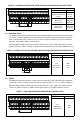
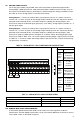
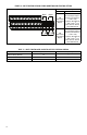
FIGURE 36 – ANALOG OUTPUTS 1 AND 2 CONNECTIONS AND FUNCTION SETTINGS
144
181715 16
1 2 3
TB1
9
23222019 21
5
6 7 8
28272524 26
10
11 12 13
SIGCOMSIG COM
Output 1 Output 2
VOLTVOLTCUR
J3
CUR
J2
Function Settings
Function No. Range/Code
8.06
Analog
Output 1
Mode
0000 – 0004
Motor Frequency,
Set Frequency,
Motor Voltage, Bus
Voltage, Motor Current
8.07
Analog
Output 1
Gain
0 – 200
Set to the
Desired Gain
8.08
Analog
Output 2
Mode
0000 – 0004
Motor Frequency,
Set Frequency,
Motor Voltage, Bus
Voltage, Motor Current
8.09
Analog
Output 2
Type
0000 – 0002
0 – 5 Volts DC,
0 – 20 mA DC,
4 – 20 mA DC
8.10
Analog
Output 2
Gain
0 – 200
Set to the
Desired Gain
TABLE 16 – ANALOG OUTPUTS 1 AND 2 ELECTRICAL RATINGS
Parameter Specification Factory setting
Analog Outputs 1 and 2 Voltage Range (Volts DC) 0 – 5 0 – 5
Analog Output 2 Current Range (mA DC) 0 – 20, 4 – 20 —
Analog Output 2 Impedance for Current Mode (Ω) 150 —