
User Guide
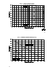
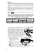
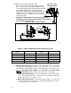
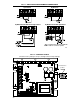
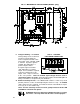
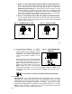
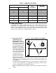
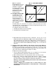
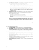
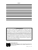

FIG. 8 – AC LINE CONNECTION
FIG. 9 – ARMATURE CONNECTION
IV. MOUNTING.
Mount the KBMG-212D on a flat surface in an atmosphere free of moisture, metal chips,
and corrosion. See Mechanical Specifications, fig. 13, p. 21. A 5K ohm remote speed
potentiometer is provided with each control. Install potentiometer using hardware
provided. Be sure to install insulating disk between potentiometer and inside of front
panel.
Enclosure – When mounting the KBMG-212D in an enclosure, it must be large enough
to allow the proper heat dissipation. A 12"12"12" enclosure is suitable when the
control is not mounted on an auxiliary heatsink. A 12"12"24" enclosure is
appropriate at full rating (11.0 amps) when the control is mounted on an auxiliary
heatsink KB P/N 9861.
V. WIRING. Warning! Read Safety Warning before attempting to use this
control.
Warning! To avoid erratic operation do not bundle AC line and motor wires with
potentiometer, voltage following, enable, inhibit or other signal wiring. Use
shielded cables on all signal wiring over 12" (30 cm) – Do not ground shield.
TABLE 6 – TERMINAL BLOCK WIRING INFORMATION
Terminal Block
Designation
Connection
Designation
Supply Wire Gauge
Maximum
Tightening
Torque (in-lbs)
Minimum Maximum
TB1 Logic Conections 22 14 3.5
15
Wire control in accordance with National Electrical
Code requirements and other local codes that
apply. A “normal blo” 20 amp fuse or circuit
breaker should be used on each AC line conductor
that is not at ground potential (do not fuse neutral or
grounded conductors). (See section VI, p. 24 for
fuse information.) Wire control in accordance with
connection diagrams (see figures 8, 9, 10A, 10B, 11
and 14 on pages 16, 17, 19 and 22). A separate AC line
switch or contactor must be wired as a disconnect switch so
that contacts open each ungrounded conductor of the control.
See table 6 for terminal block wiring information.
A. AC Line – Connect AC Line to
terminals L1 and L2. (Be sure
jumpers J1A and J1B are set to
match the AC line voltage used.)
(See table 5, p. 10.)
B. Ground – Be sure to ground (earth)
control via green screw located
on chassis.
Do not ground any other terminals.
C. Motor Armature – Connect motor armature to terminals M1 (+) and M2 (–). (Be
sure jumper J3 is set to match motor voltage.) (See table 5, p. 10.)
16