
User Guide
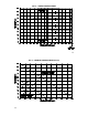
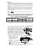
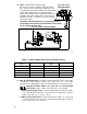
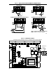
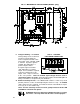
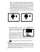
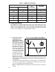
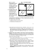
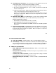
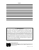

FIG. 10A – FULL
VOLTAGE FIELD
D. Field – For Shunt Wound motors only.
Do not use F+ and F– terminals for any other motor
type. Connect motor shunt field to terminals F+ and
F– for 90VDC motors with 100VDC fields and 180VDC
motors with 200VDC fields. For motors with half
voltage fields, 90VDC motors with 50VDC fields and
180VDC motors with 100VDC fields, connect field to
terminals F+ and L1. See table 7, p. 18 for summary
of field connections.
CAUTION – Shunt-Wound motors may be damaged due to
overheating if field remains powered without motor rotating
for an extended period of time.
FIG. 10B – HALF VOLTAGE FIELD
17
TABLE 7 – FIELD CONNECTIONS (Shunt Wound Motors Only)
AC Line Voltage
(VAC)
Motor Voltage
Field Voltage
(VDC)
Field Connection
115 90 100 F+, F–
115 90 50 F+, L1
230 180 200 F+, F–
230 180 100 F+, L1
230 90* 100 F+, L1
*Step Down operation (see sec. III C, p. 9).
E. Main Speed Potentiometer – The main speed potentiometer can be connected in
several ways using terminals “COM,” “+15,” “SIG” and “–15.” A 5K ohm
potentiometer is supplied with control. (A 10K potentiometer can also be used.)
(Warning! Terminals “COM,” “+15,” “SIG” and “–15" are not isolated
from AC line.) Note: Jumper J4 must be in the “15V” position.
i. Unidirectional operation only – Connect potentiometer to terminals “COM,”
“+15,” “SIG" for forward direction. To operate in reverse direction, connect to
“COM,” “SIG,” and “–15.” See fig. 11, p. 19.
ii. Bidirectional operation only – Connect to terminals “COM,” “+15,” “SIG,” and
“–15" when using reversing contacts. To operate with a potentiometer, connect
to “+15," “SIG,” and “–15." See fig. 11.
18