
User Guide
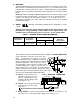
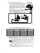
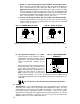
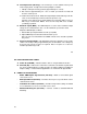

*Note: A jumper must be wired to EN and
COM in order for control to operate.
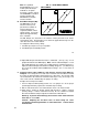
Notch denotes
position.
TRIMPOT
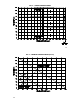
FIG. 11 – MAIN SPEED POTENTIOMETER CONNECTIONS
A) Forward B) Reverse
C) Bidirectional with Reversing Contact D) Bidirectional with Speed Pot
19
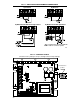
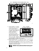
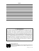
FIG. 12 – CONTROL LAYOUT
(Illustrates Factory Setting of Jumpers and Approximate Trimpot Settings)
20