
User Guide
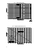
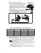
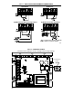
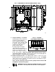
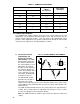
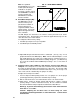
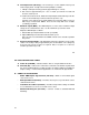
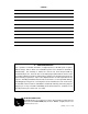

FIG. 14 – VOLTAGE
FOLLOWING CONNECTION
FIG. 13 – MECHANICAL SPECIFICATIONS (INCHES / [mm])
21
F. Voltage Following – An isolated
analog voltage can be used in lieu
of main speed potentiometer.
Connect signal to terminals “SIG"
and “COM.” Note: Terminal “COM"
is common. A positive signal to
terminal “SIG” will produce a
positive output to motor.
A negative signal to terminal
“SIG" will produce a negative
output. A 0 to ±10VDC is required
to operate control from 0 ± full
output. Note: Jumper J4 must be
in the “10V” position. Note: An isolated signal voltage must be used or
catastrophic failure can result. (A bipolar signal isolator, model SIMG [KB P/N
8832], is available as an option from your distributor.)
G. Enable Start/Stop Circuits – The KBMG-212D contains a 2-wire stop circuit
(Enable), which is used to electronically bring the motor to a “stop.” An isolated
single contact closure is required. If an isolated contact is not available, it may be
necessary to use an isolation relay.
*Note: If 2-wire start/stop circuit is not used, a jumper must be wired to EN
and COM or control will not operate.
WARNING! Do not use Start/Stop or Enable functions as a safety
disconnect. Use only an AC line disconnect for that purpose.
22