
User Guide


INSTALLATION AND OPERATING INSTRUCTIONS
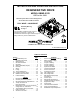
REGENERATIVE DRIVE
MODEL KBMG-212D
KB Part No. 8831
Variable Speed SCR Control Designed for
Shunt Wound and PM DC Motors
FULL WAVE • 4 QUADRANT
See Safety Warning
on Page 3
The information contained in this manual is
intended to be accurate. However, the
manufacturer retains the right to make changes in
design which may not be included herein.
A COMPLETE LINE OF MOTOR DRIVES
© 1999 KB Electronics, Inc.
TABLE OF CONTENTS
Section Page
i. Simplified Setup and
Operating Instructions .............. 1
ii. Safety Warning ................... 3
I. General Information ................ 4
II. Operation ........................ 5
III. Setting Selectable Jumpers .......... 8
IV. Mounting ....................... 15
V. Wiring ......................... 15
VI. Fusing ......................... 24
VII. Trimpot Adjustments .............. 25
VIII. Function Indicator Lamps ........... 30
IX. KBMG-212D Accessories .......... 30
X. Limited Warranty ................. 34
TABLES
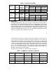
1. Electrical Ratings .................. 5
2. Summary of Control Operation ....... 6
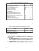
3. General Performance Specifications . 7,8
4. Jumper J2 Position vs
Motor Horsepower ................. 9
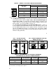
5. Relationship of AC Line Input and Motor
Voltage with J1A, J1B and J3 ....... 10
6. Terminal Block Wiring Information .... 15
7. Field Connections ................ 18
8. Armature Fuse Chart .............. 25
FIGURES Page
1. AC Line Voltage Jumper Setting .......10
2. Motor Armature Voltage
Jumper Setting ....................10
3. Jumper J4 Setting ..................11
4. Jumper J5 Setting ..................11
5. Jumper J6 Setting ..................12
6. Speed Control Mode ................13
7. Torque Control Mode ...............14
8. AC Line Connection ................16
9. Armature Connection ...............16
10A. Full Voltage Field ..................17
10B. Half Voltage Field ..................17
11. Main Speed Potentiometer
Connections ......................19
12. Control Layout ....................20
13. Mechanical Specifications ...........21
14. Voltage Following Connection ........22
15. Regenerate to Stop .................23
16. Coast to Stop .....................23
17. Tach-Generator Feedback ...........24
18. Accel Trimpot Adjustment ............26
19. Dead Band Trimpot Adjustment .......27
ii
™