
User Guide
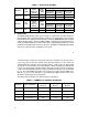
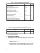

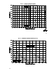

TABLE 1 – ELECTRICAL RATINGS
Model No.
KB
Part No.
AC Line
Voltage
(VAC) ± 10%
50/60 Hz
Motor
Voltage
(VDC)
Rating Without Auxiliary Heatsink
Max. AC
Load Current
(RMS Amps)
Max. DC
Load Current
(Avg. Amps)
Maximum
Horsepower
HP, (KW)
KBMG-212D 8831
115 0 – ± 90 12.0 8.0 0.75, (0.5)
230 0 – ± 180 12.0 8.0 1.5, (1.0)
Model No.
KB
Part No.
AC Line
Voltage
(VAC) ± 10%
50/60 Hz
Motor
Voltage
(VDC)
Rating With Auxiliary Heatsink (KB P/N 9861)
Max. AC
Load Current
(RMS Amps)
Max. DC
Load Current
(Avg. Amps)
Maximum
Horsepower
HP, (KW)
KBMG-212D 8831
115 0 – ± 90 16.0 11.0 1, (0.75)
230 0 – ± 180 16.0 11.0 2, (1.5)
II. OPERATION.
The KBMG-212D will vary motor speed or torque as a function of the signal voltage on
input terminals “SIG" (signal) and “COM” (common). The input voltage can be derived
from the wiper of the main speed potentiometer or from an isolated analog input (signal
voltage following mode). Since the KBMG-212D is a 4-quadrant regenerative drive, the
motor speed will follow both a positive and negative signal voltage and drive the motor
in both the forward direction and reverse direction. In addition, it will apply both forward
and reverse torque in order to stabilize motor speed.
5
To understand the concept of a regenerative drive, the operation of an elevator can be
used. If one were to enter the elevator on the first floor and press 10, the motor and
control would have to lift the elevator against gravity. In this mode, the drive would
operate like a conventional speed control which is called “motoring” (the applied load
is opposite to the direction of motor rotation). When the elevator is at floor 10 and floor
1 is pressed, gravity will try to pull the elevator car down faster than the speed for which
it is set. The control will then provide reverse torque to keep the car from falling faster
than the set speed. This operation is regeneration (the applied load is in the same
direction as the direction of motor rotation).
The table below summarizes the different modes of operation.
TABLE 2 – SUMMARY OF CONTROL OPERATION
Quadrant Type of Operation
Motor Rotation
Direction
Motor Torque
Direction
Applied Load
Direction
I Motoring CW CW CCW
II Regeneration CCW CW CCW
III Motoring CCW CCW CW
IV Regeneration CW CCW CW
6