
User Guide
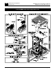
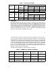
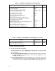
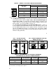

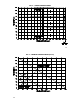

TABLE 3 – GENERAL PERFORMANCE SPECIFICATIONS
Parameter Specification
Factory
Setting
AC Line Input Voltage (VAC ±10% 50/60 Hz)
AC Line Frequency (Hz)
Armature Voltage Range 115VAC Line (VDC)
Armature Voltage Range 230VAC Line (VDC)
Field Voltage at 115VAC Line (VDC)
Field Voltage at 230VAC Line (VDC)
Max Load Capacity (% for 2 Minutes)
Ambient Temperature Operating Range (ºC)
Speed Range (Ratio)
Armature Feedback Load Regulation (% Base Speed)
Tach-generator Feedback Load Regulation (% Set Speed)
AC Line Regulation (% Base Speed)
Current Ranges (Amps DC)
Forward Accel (FACC) and Reverse Accel (RACC) Range (Sec.)
Dead Band Range (% Base Speed)
Max Speed Trimpot Range (% Base Speed)
IR Comp Range at 115VAC Line (VDC @ Full Load)
IR Comp Range at 230VAC Line (VDC @ Full Load)
115 or 230
50/60
0 – ± 90
0 – ± 90, 0 – ± 180
100/50
200/100
150
0 – 50
50:1
±1
±1
±0.5
1.7, 2.5, 5.0, 7.5, 10*
0.1 – 15
0 – ±5
55 – 110
0 – 20
0 – 40
230
—
—
0 – ± 180
—
—
—
—
—
—
—
—
7.5
1
1
100
5
10
Continued next page
7
TABLE 3 – GENERAL PERFORMANCE SPECIFICATIONS (Continued)
Parameter Specification
Factory
Setting
Forward CL (FCL) and Reverse CL (RCL) Range (% Range Setting)
Voltage Following Input Range (VDC)**
Voltage Following Linearity (% Base Speed)
0 – 175
0 – ±10, 0 – ±15
±0.5
150
0 – ±15
—
* Requires Auxiliary Heatsink KB P/N 9861.
** Requires isolated input or signal isolator.
III. SETTING SELECTABLE JUMPERS.
The KBMG-212D has customer selectable jumpers which must be set before the control
can be used (refer to fig. 1, p. 10). Bold indicates factory setting. See fig. 12, p. 20 for
location of jumpers.
A. J1A, J1B – Input AC Line Voltage – Select proper input line voltage, 115VAC or
230VAC, by placing both J1A and J1B in the correct corresponding position, “115"
or “230.” (See fig. 1, p. 10.)
B. J2 – Armature Current – Select the J2 position (1.7, 2.5, 5.0, 7.5, 10) closest to
the rated motor current. (Note: The maximum output current is set to 150% of the
J2 position, which may be readjusted using the FWD CL and REV CL trimpots.)
8