
User Guide
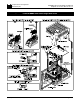
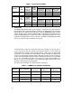
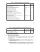
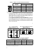


TABLE 4 – JUMPER J2 POSITION vs MOTOR HORSEPOWER
Jumper J2 Position
Motor Current
(DC Amps)
Motor Horsepower HP, (KW)
90VDC 180VDC
10.0A* 1.0, (0.75) 2.0, (1.5)
7.5A 3/4, (0.5) 1, (1.0)
5.0A 1/2, (0.37) 1.0, (0.75)
2.5A 1/4, (0.18) 1/2, (0.37)
1.7A 1/6, (0.12) 1/3, (0.25)
* 10.0A setting requires auxiliary heatsink KB P/N 9861
C. J3 – Motor Armature Voltage – Select the desired armature voltage by placing J4
in the proper position, “A90" or “A180.” Note: For 115 volt AC line input, J3
must be set to “A90.” For 230 input, the armature voltage is normally set for
“A180.” However, it is also possible to set the armature voltage to “A90" for step-
down operation. (See fig. 2 and table 5 on page 10.)
J3 – Tach-Generator Feedback (for use with 1800 RPM motors.) – Jumper J3
is also used if tach-generator feedback is to be used. (See fig. 2, p. 10) If a 7 volt
per 1000 RPM tach-generator is used, set jumper J4 in the “T7" position. For a 50
volt per 1000 RPM tach-generator, set the jumper in the “T50" position. Note:
When using tach-generator feedback, the IR Comp trimpot should be turned to a
minimum setting (full CCW).
9
FIG. 1 – AC LINE VOLTAGE
JUMPER SETTING (J1A, J1B)
115VAC 230VAC
FIG. 2 – MOTOR ARMATURE VOLTAGE
JUMPER SETTING (J3)
90VDC 180VDC
TABLE 5 – RELATIONSHIP of AC LINE INPUT AND MOTOR
VOLTAGE with J1A, J1B and J3 JUMPER POSITION
AC LINE INPUT VOLTAGE J1A, J1B POSITION J3 POSITION MOTOR VOLTAGE
115 115 90 90
230 230 180 180
230 230 90* 90*
*A 90VDC motor can be used with a 230VAC line (J3 set in “A90" position). However, speed range may
be reduced and motor derating may be required.
10