
User Guide
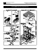
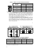


FIG. 3 – JUMPER J4 SETTING
Potentiometer Operation Signal Following
FIG. 4 – JUMPER J5 SETTING
Speed Mode Torque Mode
FIG. 5 – JUMPER J6 SETTING
Coast to Stop Regenerate to Stop
D. J4 – Analog Input Voltage –
Jumper J4 is set to the “15V”
position for potentiometer
operation. If the control is to
be operated from an isolated
0 – ±10VDC signal (see sec. V,
F, p. 22.), set J4 to the “10V”
position.
E. J5 – Control Mode (Speed or
Torque).
i. Speed ( SPD) Mode – (Note:
Factory setting of J5 is
Speed mode.) In the speed
control mode (J5 set to
SPD), the KBMG-212D will
provide variable speed
control. The motor speed
will be in direct proportion to
the input signal. Both forward and reverse torque are used to stabilize motor
speed. (See fig. 6, p. 13.)
ii. Torque (TRQ) Mode – In the torque control mode (J5 set to TRQ), the
KBMG-212D will vary the maximum motor torque as a function of the voltage
input to terminals “SIG” (signal) and “COM” (common). This voltage can be
derived from the wiper of the main potentiometer or from an isolated analog
input (signal voltage following).
11
If the motor torque is greater than the load torque, the motor will rotate. If no
load is applied to the motor, the motor will rotate at a speed proportional to the
torque setting as set by the main potentiometer (see fig. 7, p. 14). By using the
ACCEL and DECEL trimpots, the application of torque can be made more
gradual or less gradual as required by the application. A maximum torque can
be established using the current selector jumper, J2, which can be further
modified by using the FWD and REV CL trimpots.
F. J6 – Coast to Stop (CTS),
Regenerate to Stop (RTS) –
This function operates in
conjunction with the Enable
circuit, which is used to start
and stop the control
electronically. If the circuit
connecting terminals “EN” and
“COM” on terminal block TB1
are opened, the control will cause the motor to stop. When jumper J6 is in the
factory position (RTS), the motor will regenerate to a stop.
If J6 is changed to the coast to stop (CTS) position, the motor will coast to a stop
when the “EN” - “COM” circuit is opened.
Note: Control will not run unless a jumper or closed contact is connected
between the “EN” and “COM” terminals.
12