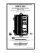
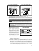
INSTALLATION AND OPERATING INSTRUCTIONS KBPC-225 SCR SPEED AND TORQUE CONTROL NEMA 4X, IP-65 DESIGNED FOR SHUNT WOUND & PM DC MOTORS RATED 3 HP @ 180 VDC TM TM See Safety Warning on Page 3 The information contained in this manual is intended to be accurate. However, the manufacturer retains the right to make changes in design which may not be included herein. (Shown with optional Run-Stop-Jog Switch) A COMPLETE LINE OF MOTOR DRIVES © 1998 KB Electronics, Inc.
TABLE OF CONTENTS Section Page i. Safety Warning . . . . . . . . . . . . . . . . . . . . . . . . . . . . . . . . . . . . . . . . . . . . . . . . . . . . . . . . . 3 ii. Simplified Operating Instructions . . . . . . . . . . . . . . . . . . . . . . . . . . . . . . . . . . . . . . . . . . . . 3 I. General Information . . . . . . . . . . . . . . . . . . . . . . . . . . . . . . . . . . . . . . . . . . . . . . . . . . . . . 3 II. Setting Speed or Torque Mode of Drive (Jumper J1) . . . . . . . . . . . . .
i. SAFETY WARNING! — PLEASE READ CAREFULLY This product should be installed and serviced by a qualified technician, electrician or electrical maintenance person familiar with its operation and the hazards involved.
The electronics for the KBPC is state-of-the-art and includes short circuit and transient protection which provides the ultimate in reliability. Electronic overload protection prevents motor burnout and demagnetization of PM motors. The control can be operated in either the Speed or Torque mode via jumper selection. Standard features include electronic start/stop and an LED indicator array for Power On, Stop and Overload.
FIG.
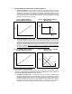
II. SETTING SPEED OR TORQUE MODE OF DRIVE (JUMPER J1) A. Speed Control Mode – When Jumper J1 is placed in the "SPD" position the drive will control motor speed as a linear function of the main potentiometer rotation or analog voltage input. The range of output speed can be adjusted with the MIN and MAX trimpots. The motor will maintain the preset speed as long as the maximum load does not exceed the current limit set point.
B. J5 - Current Limit Mode – (Factory set for "TCL") This control contains electronic current limiting which limits the maximum DC current to the motor (the current limit set point is established with the setting of the CL trimpot). Two modes of current limit operation are provided: 1. Timed Current Limit "TCL" – In this mode the drive will turn off after being in current limit for a preset time. This time period is adjustable with the TCL trimpot from 0.
FIG. 4A – CAPTIVE SCREW TIGHTENED IN CASE FIG. 4B – CAPTIVE SCREW ENGAGED IN FRONT COVER CAPTIVE SCREW CAPTIVE SCREW COVER COVER GASKET GASKET CASE CASE V. WIRING WARNING! – Read Safety Warning on page 3 before attempting to use this control. Wire control in accordance with the National Electric Code requirements and other codes that apply. Be sure to fuse each conductor which is not at ground potential. Do not fuse neutral or grounded conductors. Note: See Section VI. Fusing (p.10).
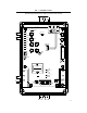
FIG. 6A – FULL VOLTAGE FIELD FIG. 6B – HALF VOLTAGE FIELD 180 VDC MOTORS WITH 200 VDC FIELDS F1 F2 A1 A2 L1 180 VDC MOTORS WITH 100 VDC FIELDS L2 TB2 F1 F2 TB1 + A1 A2 L1 L2 TB2 – TB1 + + – + FIELD – FIELD ARM ARM AC LINE AC LINE D. Ground – Be sure to ground (earth) the control by connecting a ground wire to the Green Ground Screw located to the right of the terminal block. (See Fig. 1, p. 5) E.
FIG. 8A – REMOTE POTENTIOMETER CONNECTION FIG. 8B – ANALOG VOLTAGE CONNECTION P3 P2 P1 G. Remote Start/Stop Switch – A remote Start/Stop Switch can be installed by removing the wires from the "Start," "Com" and "Stop" terminals, and reconnecting them to a remote switch. (See Fig. 9) Note: To eliminate Start/Stop function, join the "Start" and "Com" Quick Connect terminals with a jumper. H. Inhibit – The control can be electronically stopped and started with the Inhibit circuit.
VII. OPERATION. WARNING! Read Safety Warning on page 3 before attempting to operate the control or severe injury or death can result. After the control has been set up properly (the jumpers set to the desired positions, and the wiring has been completed) the start-up procedure can begin. If AC power has been properly brought to the control the "ON" LED and the "STOP" LED indicators will be lighted. Before initially starting, be sure the main potentiometer is in the minimum position.
E. Current Limit (CL) – This trimpot is used to set the maximum amount of DC current that the motor can draw. The amount of DC current determines the amount of maximum motor torque in both the Speed Control Mode and Torque Mode. The CL trimpot is factory set at 150% of the motor current (approx. 22 amps). Also see section IX C. Readjust the CL trimpot as follows: 1. When jumper J1 is set to the Speed Control Mode, the main potentiometer should be set at 50% rotation.
2. Motor may be defective - check motor for shorts or grounds. 3. The CL may be set too low - check position of CL trimpot. NOTE: In some applications, especially those requiring the motor to cycle on and off or changing from one speed to another, the OL indicator may blink indicating a transient overload. This may be a normal condition for the application. X. OPTIONAL ACCESSORIES A.
TM TM FIG.
FIG.
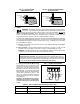
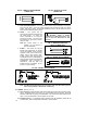
L1 L2 SIGNAL IN ( 0 – 10 VDC) 1. KBSI-240D IS SHOWN WIRED FOR 230 VAC LINE 2. OTHER SIGNAL RANGES AVAILABLE. (SEE KBSI-240D INSTRUCTION MANUAL.) NOTES SIGNAL IN ( 0 – 10 VDC) 10 9 8 BLU BLU WHT WHT RED KBSI-240D WHT ORN AUTO MAN ORN VLT SIGNAL FOLLOWING AUTOMATIC MODE WITH MANUAL OVERRIDE P3 P2 P1 INSTALLATION KIT WIRES SHOWN IN BOLD LINES 9 10 8 7 ” MALE QD TERMINAL 4 5 2 3 1 6 P2 P1 KBPC-225 7 KBSI-240D 4 5 6 2 3 1 SIGNAL FOLLOWING AUTOMATIC MODE FIG.
XI. – LIMITED WARRANTY For a period of 18 months from date of original purchase, KB will repair or replace without charge devices which our examination proves to be defective in material or workmanship. This warranty is valid if the unit has not been tampered with by unauthorized persons, misused, abused, or improperly installed and has been used in accordance with the instructions and/or ratings supplied.