
User Guide

6
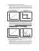
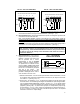
II. SETTING SPEED OR TORQUE MODE OF DRIVE (JUMPER J1)
A. Speed Control Mode – When Jumper J1 is placed in the "SPD" position the drive will
control motor speed as a linear function of the main potentiometer rotation or analog
voltage input. The range of output speed can be adjusted with the MIN and MAX trimpots.
The motor will maintain the preset speed as long as the maximum load does not exceed
the current limit set point. If the motor load exceeds the current limit setting, the Overload
LED will turn on and the motor will stall.
FIG. 2A – MOTOR SPEED vs.
POTENTIOMETER ROTATION
MOTOR
OUTPUT
SPEED
(%)
POTENTIOMETER ROTATION (%)
0
100
100
FIG. 2B – PRESET MOTOR SPEED vs.
MOTOR LOAD
PRESET
MOTOR
SPEED
(%)
MOTOR LOAD
100
0
150
CURRENT LIMIT STARTS
LED LIGHTS
100
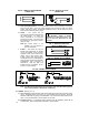
B. Torque Control Mode – When Jumper J1 is placed in the "TRQ" position, the drive will
control motor torque as a linear function of main potentiometer rotation. If the motor load
exceeds the torque setting, the motor will stall, the Overload LED will light, and the drive
will apply a constant preset torque based on the potentiometer setting. The Overload LED
will light when the load torque approaches the current limit set point. The torque limits are
set via the CL trimpot. Note: When operating in the Torque Mode, Jumper J5 must be in
the "NTCL" position or drive will shut down when CL Timer times out.
FIG. 3A – MOTOR OUTPUT TORQUE vs.
POTENTIOMETER ROTATION
POTENTIOMETER ROTATION (%)
150
0
100
MOTOR
OUTPUT
TORQUE
(%)
100
FIG. 3B – MOTOR SPEED vs. APPLIED
MOTOR LOAD
100
APPLIED MOTOR LOAD (%) TORQUE
MOTOR
SPEED
(%)
HIGHER TORQUE
SETTING
TORQUE
SETTING
S3
S2
S1
LOWER TORQUE
SETTING
0
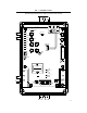
III. SETTING SELECTABLE JUMPERS
This control has selectable jumpers which can be changed to accommodate various
applications. Note: Jumpers J2 and J4 have not been installed in this control. Jumper J1
is set in accordance with Section II. Refer to Figure 1.
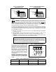
C. Tachometer Feedback (J3) – The control is factory set for armature feedback which
provides good load regulation for most applications. If superior load regulation is required,
tachometer feedback can provide over 1% load regulation over a 50:1 speed range. If
tachometer feedback is to be used, J3 must be placed in the "TFB" position and an external
DC tachometer must be connected. See Sections III C. (p. 7) and V E. (p. 9) for additional
information. Note: IR Comp trimpot must be turned to minimum position (full ccw).