
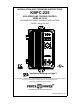
User Guide
7
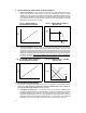
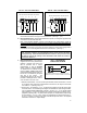
B. J5 - Current Limit Mode – (Factory set for "TCL") This control contains electronic current
limiting which limits the maximum DC current to the motor (the current limit set point is
established with the setting of the CL trimpot). Two modes of current limit operation are
provided:
1. Timed Current Limit "TCL" – In this mode the drive will turn off after being in current limit
for a preset time. This time period is adjustable with the TCL trimpot from 0.5-15
seconds and is factory set for approximately seven (7) seconds. This provides motor
overload protection.
Applicatin Note – After the control times out in TCL, it can be reset using the Start
Switch by setting the switch to the "STOP" position and then to "START," or by
disconnecting and reconnecting the AC line. If the Start Switch is jumpered out, the
control can be restarted after timing out in TCL, by disconnecting and reconnecting the
AC line. Note: The Overload lamp will remain lighted until the control is reset.
2. Non-Timed Current Limit "NTCL" – In this mode the drive will reach the preset current
limit during overload and stay at that level until a fuse blows or the drive is manually
turned off. If non-timed CL operation is desired, move jumper J5 from the factory set
"TCL" position to the "NTCL" position. The NTCL position must be used when operating
in the Torque Mode. See Sec. II B. (p.6).
C. J6 - Tachometer Voltage – (Note: Selection of this jumper position is not required if
tachometer feedback is not used.) If tachometer feedback is used, select the J6 position
(7V, 20/30V, 50V) which corresponds to the tachometer voltage in Volts/1000 RPM. The
selection of J6 position is based on a maximum motor speed of 1800 RPM. If other than
standard tachometer voltages and motor speeds are used, an external resistor (RT) may
be used (1/2 watt rating).
1. Install resistor (RT) in series with either tachometer lead.
2. Place J6 in "7V" position.
3. Calculate the value of (RT) as follows:
RT = [(0.9 x VT x S) - 20,000] ohms VT = Tach Voltage in Volts/1000 RPM
S = Base speed of motor in RPM
Note: For tachometer feedback, Jumper J3 must be in the "TFB" position, and IR
Comp trimpot must be set to minimum (ccw) position.
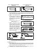
D. J7 - Signal Input Voltage – The output of this control is normally controlled with the main
potentiometer. However, an Isolated analog voltage may also be used in place of a
potentiometer. The control can be scaled for either a 0-5VDC or 0-10VDC by placing J7
in the appropriate position "5V" or "10V". The scaling can be further adjusted with the
"Max" trimpot. (See Sec. V, F 2., (p. 9), for wiring information.)
Note: If an Isolated input signal is not available, an accessory Signal Isolator Model KBSI-
240D (KB P/N 9431) can be installed. The KBSI-240D accepts a wide range of signal
voltage and current. An Installation Kit containing Auto/Man Switch and required wiring is
als available (P/N 9377).
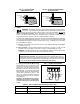
IV. Mounting
Mount the control in a vertical position on a flat surface. Be sure to leave enough room below
the bottom of the control to allow for the AC line and motor connections. Although the control
is designed for outdoor and washdown use, care should be taken to avoid extremely hazardous
locations where physical damage can occur. Note: Do not use this control in an explosion
proof application. If the control is mounted in a closed, unventilated cabinet, remember to
allow for proper heat dissipation. If full rating is required, a minimum enclosure size of 12" W
x 24" H x 12" D should be used.
Front Cover - The KBPC case is designed with a hinge so that when the front cover is open,
all wiring stays intact. To open the cover, the four cover screws must be loosened, so they no
longer are engaged in the case bottom. Note that these screws are captive and the front cover
holes are threaded. After mounting and wiring, close the front cover, making sure all wires are
contained within the enclosure and the gasket is in place around the cover lip. Tighten all four
cover screws so that the gasket is slightly compressed. Do not overtighten.