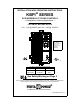
INSTALLATION AND OPERATING INSTRUCTIONS KBPI SERIES SCR INDEXING & CYCLING CONTROLS — Designed for Indexing Applications — FOR PM DC MOTORS RATED (1/6 – 1 HP @ 90VDC) and (1/3 – 2 HP @ 180VDC) TM This control will not operate without installing the correct armature fuse – supplied separately. See Page 2 TM This Manual Covers the Following Models Model No. Operation Part No.
TABLE OF CONTENTS Section Page i. Simplified Setup and Operating Procedures . . . . . . . . . . . . . . . . . . . . . . . . . . . . . . . . . . . . . . 1 ii. Safety Warning . . . . . . . . . . . . . . . . . . . . . . . . . . . . . . . . . . . . . . . . . . . . . . . . . . . . . . . . . . . . 2 I. General Information . . . . . . . . . . . . . . . . . . . . . . . . . . . . . . . . . . . . . . . . . . . . . . . . . . . . . . . . . 2 II. Mounting . . . . . . . . . . . . . . . . . . . . . . . . . . . . . . . . .
i. SIMPLIFIED SETUP AND OPERATING PROCEDURES Before operating this control you must read these instructions. They are to be used as a reference only and are not intended to replace the detailed instructions provided herein. You must read the Safety Warning before proceeding. 1. AC Power – Be sure jumpers J2A and J2B on power board and jumper ”J1” on logic board are set to the correct positions to match the AC line input voltage. (See table 4, p. 9.
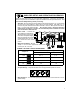
ii. SAFETY WARNING! — PLEASE READ CAREFULLY This product should be installed and serviced by a qualified technician, electrician or electrical maintenance person familiar with its operation and the hazards involved.
8500 8501 KBPI-240D KBPI-240DR 0 – 90* 240 0 – 90 120 0 – 180 0 – 90* 240 240 0 – 180 0 – 90 120 240 Motor Armature Voltage (VDC) Input Line Voltage (VAC 50/60 Hz ±10%) 15.0 15.0 15.0 15.0 15.0 15.0 Maximum AC Load Current (RMS Amps) NOTE: Motor performance and brush life may be affected. *Denotes step-down operation. A 90 Vdc motor used on a 240 VAC line input. Part Number Model Number 10/2 10.2 10.2 10.2 10.2 10.
FIG.
FIG.
TABLE 2 – GENERAL PERFORMANCE SPECIFICATIONS Specifications Parameter (Units) AC Line Input (VAC ± 10%, 50/60 Hz) Model No. KBPI-240D (P/N 8500) & Model No. KBPI-240DR (P/N 8501) Factory Setting 120 240 240 Horsepower Range (HP) [KW] 1/6 - 1, [.12 - .75] 1/3 - 2, [.25 - 1.5] 2, [1.5] Armature Voltage Range (VDC) 0 – 100 0 – 200 170 Current Ranges (ADC) 2, 3.3, 5, 10 10 CL Trimpot Range (% Range Setting) 0 – 170 150 Min. Speed Trimpot Range (% base spd) 0 – 30 0 Max.
TABLE 3 – SELECTABLE JUMPER REFERENCE CHART Jumper Location* Description Factory Setting J1 1 Establishes the range of maximum armature current. See sec. IV, p. 9. J2A, J2B 1 Sets the AC input line voltage (120/240 VAC) for the main PC Board. Set according to model part numbers. See table 1, p. 3. J3 1 Sets the DC output voltage range to motor (90V/180V). Set according to model part numbers. See table 1, p. 3. 1 Used to activate the return (RTN) circuit.
8 TM TM FIG.
III. SETTING AC LINE AND MOTOR VOLTAGE. The KBPI is factory set to operate with a 230VAC - 50/60 Hz AC line input and a 180-VDC PM motor. By utilizing jumpers J2A, J2B and J3 on the main PC board and Jumper J1 on the logic PC board, different AC line voltage/motor voltage combinations can be achieved. A. B. C.
V. WIRING WARNING! Read Safety Warning on page 2 before attempting to use this control. Wire control in accordance with the National Electric Code requirements and other codes that apply. Be sure to fuse each conductor which is not at ground potential. Failure to follow the Safety Warning Instructions may result in electric shock, fire or explosion. Do not fuse neutral or grounded conductors. Note: See sec. VI, p.11 Fusing.
C. Ground – Be sure to ground (earth) the control by connecting a ground wire to the Green Ground Screw located to the right of the terminal block. Do not connect ground wire to any other terminals on control. FIG. 5 – REMOTE POTENTIOMETER CONNECTION D. Main Potentiometer – The control is supplied with the main potentiometer prewired. However, the control can also be operated from a remote potentiometer, or FIG. 6 – ANALOG VOLTAGE from an isolated analog voltage for voltage CONNECTION following.
VII. LOGIC FUNCTIONS AND WIRING. Warning! Do not use any of the logic functions (STP, RTN) as an emergency stop since they are not fail safe. Use only an AC line (L1, L2) disconnect for that purpose. To prevent erratic operation, do not bundle logic wiring with AC line and motor wires. Use shielded cables on logic wiring over 12" (30 cm) in length. Do not ground or common shield. The control contains several logic functions which are described in detail below. connections are made to terminal block TB3.
C. "STOP" (STP) — Use FIG. 10 – STOP COMMAND a nor-mally closed (NC) contact between terminals "STP" and "RTN." Opening the contact activates the control’s Dynamic Brake producing a rapid stop. (Note: A normally open (NO) limit switch or contact can also be used to activate the stop command. To use a (NO) contact move jumper JS to the "NO" position). (See table 3, p. 7.) Application Note: The setting of jumper "JW" establishes the priority a "STOP" command has over a "RUN" command.
FIG. 11 – JUMPER “JR” OPERATION Jumper "JR" in "F" position (factory setting) connects "RTN" to "COM" Jumper "JR" in "O" position opens the "RTN" to "COM" circuit allowing the use of an external disable contact. This will not stop indexer in run mode. E. +24 VDC SUPPLY – The +24V terminal provides a nominal1 24 VDC @ 12 mA output for use with an external load such as one solid-state 3-wire proximity switch. F.
Example 3: “Cycle on Demand” – Important Information In a “Cycle on Demand” application, the Indexer Drive will make one complete cycle of movement of table or conveyor and then dwell until it receives an external signal from the machine's controller or operator to start again. If motor receives a signal to start while the Indexer Drive is in its dwell position, the motor will accelerate from a paused position to full speed during one half of the dwell of the main indexer cam.
The "Cycle on Demand" function is required for most indexing table applications. The control can be easily set for this operation as follows: 1. Jumper "JW" must be in the "R" position (factory setting) see table 8, p. 13. FIG. 15 – CYCLE ON DEMAND WIRING TB3 2. Jumper "JR" must be in the "F" position (factory setting) see sec. VII, D, p. 13. MOMENTARY START SWITCH (N/O) 3. Wire limit switch LS1 (normally closed) and start switch (normally open) as shown.
IX. APPLICATION WIRING DIAGRAMS Reversible Model KBPI-240DR (120/240 VAC) Reversing models carry out the same functions as the unidirectional models except they can be made to index in both the forward and reverse direction. A special circuit APRM® provides a lockout feature that prevents catastrophic damage to the drive if a "Reverse" command is given during "Forward" operation (and vice versa). The reversing drives contain two additional positions on the terminal block: "Run Rev" and "Jog Rev.
X. OPERATION. WARNING! Read Safety Warning on page 2 before attempting to operate the control or severe injury or death can result. Failure to follow the Safety Warning Instructions may result in electric shock, fire or explosion. After the control has been set up properly (the jumpers set to the desired positions and the wiring completed), the start-up procedure can begin. If AC power has been properly brought to the control, the "ON" and the "STOP" indicators will be lighted.
CAUTION: 1. Adjusting the CL above 150% of motor rating can cause overheating and demagnetization of some PM motors. Consult motor manufacturer. 2. Do not leave the motor in a locked condition for more than a few seconds since armature damage may occur. D. IR Compensation (IR) – The IR Comp circuit is used to stabilize motor speed under varying loads. Readjust the IR trimpot as follows: 1. Run the motor at approximately 30-50% of rated speed under no load and measure actual speed. 2.
XIII – TROUBLESHOOTING GUIDE MOTOR WILL NOT RUN: 1. Check control operation by placing RUN - JOG/STOP in RUN position. 2. Make sure disconnect fuses or circuit breaker in AC line are okay. 3. Check fuse on PC board and if open, replace. 4. Check logic. See Start-up Procedures and Application Section. 5. Be sure speed pot is not set at zero. 6. Unit is in current limit – See if "OL" indicator is lighted. Check position of jumper J1. (See table 5, p. 9) and CL trimpot setting. 7.
21
XIV – LIMITED WARRANTY For a period of 18 months from date of original purchase, KB will repair or replace without charge devices which our examination proves to be defective in material or workmanship. This warranty is valid if the unit has not been tampered with by unauthorized persons, misused, abused, or improperly installed and has been used in accordance with the instructions and/or ratings supplied.