
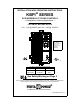
Owner manual


1
i. SIMPLIFIED SETUP AND OPERATING PROCEDURES
Before operating this control you must read these instructions. They are to be used as a
reference only and are not intended to replace the detailed instructions provided herein. You
must read the Safety Warning before proceeding.
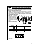
1. AC Power – Be sure jumpers J2A and J2B on power board and jumper ”J1” on logic board
are set to the correct positions to match the AC line input voltage. (See table 4, p. 9.)
Connect AC power to terminal block TB1 terminals L1 and L2. When power is turned on,
LED 1 on main power board will light. . Be sure AC power is disconnected when
making other connections to control. Do not bundle AC power and motor wires with
wires connected to TB3 terminals.
2. Motor Leads – Connect the
motor leads to terminal block
TB2 terminals A1 and A2. Be
sure motor nameplate voltage
rating corresponds to control
output voltage rating. Do not
use control with shunt wound
motors.
3. Motor Current Setting – Be sure
Jumper J1 is set to the approximate rated motor
current (10A, 5A, 3.3A, 2A).
JUMPER J1 SETTING vs MOTOR HORSEPOWER
Jumper J1*
Motor Horsepower Range
90 VDC 180 VDC
10A 3/4 – 1 1 – 2
5A Ω 1
3.3A 1/4 – 1/3 1/2 – 3/4
2A 1/6 1/3
*Note: Jumper J1 is shown in the factory setting.
4. Trimpot Settings – Trimpots should be set to the approximate positon as shown:
5. Main Speed Pot – Turn the main speed pot on the front cover of the control to a 15% or
greater setting.