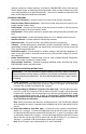
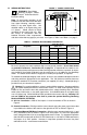
INSTALLATION AND OPERATION MANUAL MODEL KBPW-240D KB Part No. 8401 (Black Case) • Part No. 8402 (White Case) NEMA 4X, IP-65 PWM DC Motor Speed Control For PM and Shunt Wound Motors Rated 7.5 Amps DC, 11.5 Amps AC @ 115/230 VAC ON STOP OL PENTA-DRIVE™ PWM DC MOTOR SPEED CONTROL 50 40 60 70 30 20 80 10 90 0 100 % FWD BRK REV NEMA-4X / IP-65 START RUN STOP JOG ™ ! See Safety Warning on Page 2 The information contained in this manual is intended to be accurate.
TABLE OF CONTENTS Section Page i. Safety Warning . . . . . . . . . . . . . . . . . . . . . . . . . . . . . . . . . . . . . . . . . . . . . . . . . . . . . . . . . . 1 I. Introduction . . . . . . . . . . . . . . . . . . . . . . . . . . . . . . . . . . . . . . . . . . . . . . . . . . . . . . . . . . . . . 1 II. Simplified Operating Instructions . . . . . . . . . . . . . . . . . . . . . . . . . . . . . . . . . . . . . . . . . . . . . 2 III. Wiring Instructions . . . . . . . . . . . . . . . . . . . . .
20. Run Relay Output Mode Selection (J5) . . . . . . . . . . . . . . . . . . . . . . . . . . . . . . . . . . . . . . . 12 21. Stop Switch Type Selection (J6) . . . . . . . . . . . . . . . . . . . . . . . . . . . . . . . . . . . . . . . . . . . . 12 22. Enable Selection . . . . . . . . . . . . . . . . . . . . . . . . . . . . . . . . . . . . . . . . . . . . . . . . . . . . . . . . 12 23. ACCEL Trimpot Range . . . . . . . . . . . . . . . . . . . . . . . . . . . . . . . . . . . . . . . . . . . . . . . . . . .
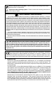
Electrical Hazard Warning Symbol: Failure to observe this warning could result in electrical shock or electrocution. ! Operational Hazard Warning Symbol: Failure to observe this warning could result in serious injury or death. i. ! SAFETY WARNING! Please read carefully This product should be installed and serviced by a qualified technician, electrician, or electrical maintenance person familiar with its operation and the hazards involved.
Optional accessories include On/Off AC Line Switch, FWD-BRK-REV Switch, Run-Stop-Jog Switch, Signal Isolator, and Anti-Plug Reversing Module. Quick-connect terminals are provided for easy installation of all optional accessories. The control is available in black finish (P/N 8401) and FDA approved white finish (P/N 8402). STANDARD FEATURES • Short Circuit Protection – Protects control from a short circuit at motor connections.
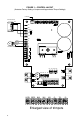
D. Motor Current – Jumper J2 is factory set for 7.5 Amp motors. For lower current motors, set jumper J2 to the corresponding motor current as described in Section IVB, on page 10. Note: The factory setting for Current Limit is 150% of the nominal current setting (example: if jumper J2 is set to “5A” position, the CL trimpot is calibrated for 7.5 Amps). E. Trimpot Settings – All trimpots have been factory set as shown in Figure 1, on page 4.
FIGURE 1 – CONTROL LAYOUT (Illustrates Factory Setting of Jumpers and Approximate Trimpot Settings) To LED Board ACCEL DECEL MAX START/STOP SWITCH MIN JOG CL TCL IR KBPW-240D RED CON1 BLACK INH2 INH1 INH2 WHITE COM NC RELAY JOG J5 NC NO TT+ EN2 EN1 J4 J1 T 180V J2 90V TACH K1 EN J7 ENABLE P2 P2 P1 TB3 K2 RELAY P3 P1 MAIN SPEED POTENTIOMETER NO STOP ORANGE WHITE STOP COM START START J6 P3 JOG STOP VIOLET J3 TCL NTCL INH1 7V 50V BLU BLU WHT WHT ORN RED WHT BLK J7A
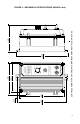
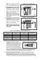
.88 225 0.36 9 STOP OL FWD 60 0 RUN JOG START STOP NEMA-4X / IP-65 REV ™ 100 10 BRK 80 90 20 % 70 50 30 40 PWM DC MOTOR SPEED CONTROL PENTA-DRIVE™ ON 9.49 241 5.00 127 CONTROL SHOWN WITH OPTIONAL FWD-BRK-REV AND RUN-STOP-JOG SWITCHES 8.23 209 5.89 150 5.
III. FIGURE 3 – POWER CONNECTION WIRING INSTRUCTIONS WARNING! Read Safety Warning, on page 1, before using this control. Disconnect the AC line before wiring. ! TB1 TB2 F1 F2 A1 A2 L1 L2 Note: To avoid erratic operation, do not bundle AC line and motor wires with wires + from signal following, start/stop switch, inhibit, or any other signal wires. Use M shielded cables on all signal wiring over 12” (30cm). Shield should be Earth GROUND AC LINE MOTOR grounded on the control side only.
Note: Do not connect motor armature leads to F1 and F2 terminals. Do not use F1 and F2 terminals for PM motors. D. Full Voltage Field Connection (Shunt Wound Motors Only) – Wire the motor field leads to F1 (+) and F2 (-) terminals of TB2 as shown in Figure 4 & Table 4. Note: Do not connect motor armature leads to F1 and F2 terminals. FIGURE 4 – FULL VOLTAGE FIELD TB1 TB2 F1 Note: Do not connect motor armature leads to F1 and F2 terminals.
STOP FIGURE 7A – REMOTE 3-WIRE START/STOP SWITCH in the front cover. Connect the WITH NORMALLY OPEN START CONTACT remote Start/Stop switch wires to AND NORMALLY OPEN STOP CONTACT START (momentary), COM (common), and STOP (constant) Start terminals as shown in Figure 7A. J6 MOMENTARY START NO CONTACT After applying power, momentariCOM ly set the Start/Stop switch to NC MAINTAINED “START” position. The motor will STOP CONTACT Stop operate at the set speed of the main speed potentiometer.
Note: If an isolated signal voltage is not available, an optional signal isolator can be installed (KBSI-240D, P/N 9431). Connect the isolated signal voltage to P2 (+) and P1 (-) terminals. Adjustment of the MIN trimpot may be necessary to achieve a 0 Volt DC output. FIGURE 10 – INHIBIT CIRCUIT INHIBIT (CLOSE TO STOP) (OPEN TO RUN) INH1 RELAY INH2 J. Inhibit Connection – The control is supplied with inhibit terminals (INH1 and INH2) to connect an Inhibit switch. See Figure 10.
FIGURE 14 – MOTOR VOLTAGE SELECTION A. Motor Voltage Selection (J1) – Jumper J1 is factory set to “90V” position for 90 Volt SCR rated motors (or 130 Volt PWM rated motors). For 180 Volt SCR rated motors (or 220 Volt PWM rated motors), set jumper J1 to “180V” position. See Figure 14. Note: If jumper J1 is set to “T” position, a tach-generator must be wired to TB3. If a tach-generator is not used, jumper J1 must be in either “90V” or “180V” position.
C. Timed and Non-Timed Current Limit Selection (J3) – Jumper J3 is factory set to “TCL” position for timed current limiting operation. See Figure 17. For non-timed current limiting operation, set jumper J3 to “NTCL” position.
FIGURE 19 – DC TACH-GENERATOR WITH ADDITION OF RT F. Stop Switch Type Selection (J6) – Jumper J6 is factory set to the “NO” position for a normally open stop switch, as used on the front cover. If a remote normally closed stop switch is used, set Jumper J6 to the “NC” position. If a remote normally open stop switch is used, set Jumper J6 to the “NO” position. See Figure 21.
potentiometer is fully counterclockwise. To start the control, momentarily set the Start/Stop switch to “START” position and release it. The STOP LED should no longer illuminate. The motor should begin to rotate, as the main speed potentiometer is rotated clockwise. Note: If the motor rotates in the incorrect direction, it will be necessary to disconnect the AC line, reverse the motor leads, and repeat the startup procedure. VII. AC LINE FUSING This control does not contain AC line fuses.
E. Jog Speed (JOG) – Sets “jog” speed of the motor. The JOG trimpot is factory set for 15% of motor base speed, as shown in Figure 27 . For a higher jog setting, rotate the trimpot clockwise. For a lower jog setting, rotate the trimpot counterclockwise. Note: The Jog feature requires installation of the Run-Stop-Jog Switch assembly (P/N 9340). F. Current Limit (CL) – Sets current limit (overload), which limits the maximum current to the motor.
B. Stop (STOP) – The STOP LED will illuminate yellow when the Start/Stop switch is set to “STOP” position. When AC line is applied, this LED will also be illuminated until the Start/Stop switch is set to “START” position. C. Overload (OL) – The OL LED will illuminate red when the control goes into current limit, indicating that the current limit set point has been reached (set by the CL trimpot and the position of jumper J2).
– NOTES – 16
XI. LIMITED WARRANTY For a period of 18 months from the date of original purchase, KB Electronics, Inc. will repair or replace, without charge, devices which our examination proves to be defective in material or workmanship. This warranty is valid if the unit has not been tampered with by unauthorized persons, misused, abused, or improperly installed and has been used in accordance with the instructions and/or ratings supplied.