
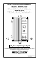
User Guide

Note: Do not connect motor armature
leads to F1 and F2 terminals. Do not
use F1 and F2 terminals for PM motors.
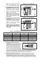
D. Full Voltage Field Connection (Shunt
Wound Motors Only) – Wire the motor
field leads to F1 (+) and F2 (-) terminals
of TB2 as shown in Figure 4 & Table 4.
Note: Do not connect motor armature
leads to F1 and F2 terminals.
Warning! Do not use F1 and F2 ter-
minals of TB2 for any purpose other
than to power the field of a shunt
wound motor.
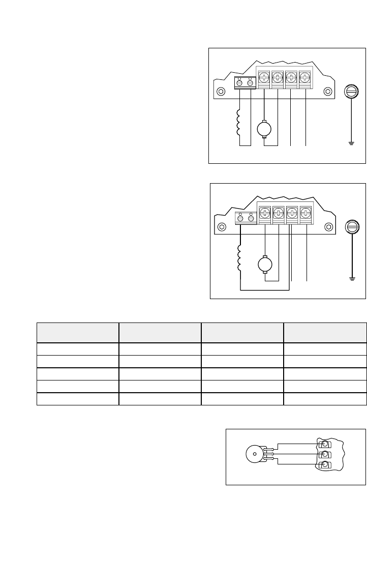
E. Half Voltage Field Connection (Shunt
Wound Motors Only) – Wire the motor
field leads to F1 (+) and L1 (-) terminals
of TB2, as shown in Figure 5 & Table 4.
Note: Do not connect motor armature
leads to F1 and F2 terminals.
Warning! Do not use F1 and F2 ter-
minals of TB2 for any purpose other
than to power the field of a shunt
wound motor.
F. Remote Main Speed Potentiometer
Connection –
The control is supplied with a
prewired main speed potentiometer mounted
on the front cover. To operate the control
from a remote potentiometer (5kΩ), remove
the white, orange, and violet potentiometer
leads from P1, P2, and P3 terminals, respec-
tively. The leads may be taped and left inside
the control. The potentiometer assembly may be removed if a watertight seal is used to
cover the hole in the front cover. Connect the remote main speed potentiometer wires to
terminals P1 (low side), P2 (wiper), and P3 (high side) as shown in Figure 6.
G. Remote Start/Stop Switch Connections – The control is supplied with a prewired
Start/Stop switch mounted on the front cover. To operate the control from a remote
Start/Stop switch (type: (ON)-OFF-ON, SPDT), remove the white, black, and red wires
from START, COM, and STOP terminals, respectively. The leads may be taped and left in
the control. The switch itself may be removed if a watertight seal is used to cover the hole
7
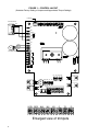
M
+
-
MOTOR
AC LINE
-
FIELD
L2L1A1 A2
TB2
TB1
F1 F2
+
GROUND
(EARTH)
FIGURE 4 – FULL VOLTAGE FIELD
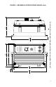
AC LINE
-
-
+
+
MOTOR
M
(EARTH)
FIELD
GROUND
L2L1A2A1
TB2
F1 F2
TB1
FIGURE 5 – HALF VOLTAGE FIELD
Field Connections
F1 & L1
AC Line Voltage
(Volts AC)
Armature Voltage
(Volts DC)
Field Voltage
(Volts DC)
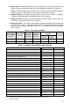
90 – 130115
115
230 180 – 260
230
230
90 – 130
180 – 260
90 – 130
100
50
200
100
100
F1 & F2
F1 & L1
F1 & F2
F1 & L1
TABLE 4 – FIELD CONNECTION (Shunt Wound Motors Only)
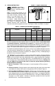
(FRONT VIEW)
Wiper
Low Side
High Side
POTENTIOMETER
MAIN SPEED
P3
P2
P1
FIGURE 6 – REMOTE POTENTIOMETER