
User Guide
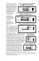

potentiometer is fully counterclockwise. To start the control, momentarily set the Start/Stop
switch to “START” position and release it. The STOP LED should no longer illuminate. The
motor should begin to rotate, as the main speed potentiometer is rotated clockwise.
Note: If the motor rotates in the incorrect direction, it will be necessary to disconnect the AC
line, reverse the motor leads, and repeat the startup procedure.
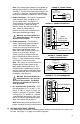
VII. AC LINE FUSING
This control does not contain AC line fuses. Most electrical codes require that each unground-
ed conductor contain circuit protection. Installation of a 20 Amp fuse or circuit breaker in series
with each ungrounded conductor is recommended. Check all electrical codes that apply to the
application.
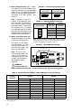
VIII. TRIMPOT ADJUSTMENTS
The KBPW-240D contains trimpots, which are factory set for most
applications. The trimpots are shown in the approximate calibrat-
ed positions. Some applications may require readjustment of the
trimpots in order to tailor the control for a specific requirement.
Readjust trimpots as described below.
Warning! If possible, do not adjust trimpots with
main power applied. If adjustments are made with
main power applied, an insulated adjustment tool must be
used and safety glasses must be worn. High voltage exists in
this control. Fire and/or electrocution can result if caution is
not exercised. Safety Warning, on page 1, must be read and
understood before proceeding.
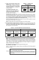
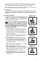
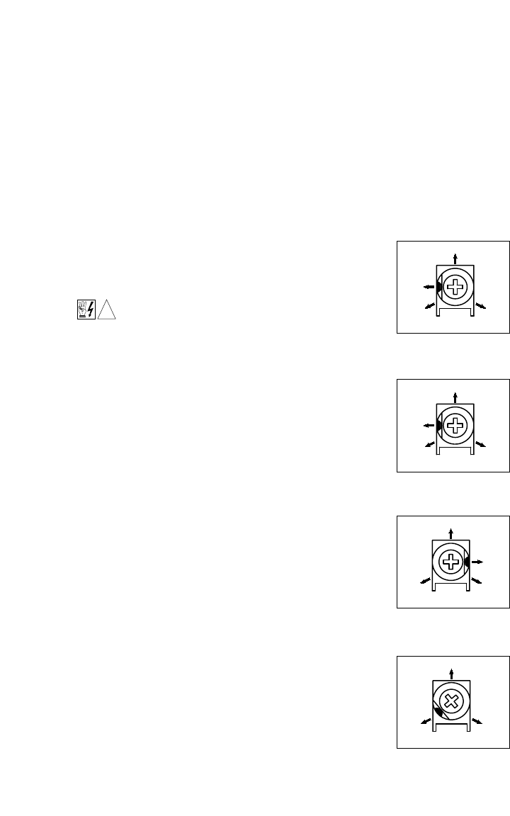
A. Acceleration (ACCEL) –
Sets the amount of time for the
motor to accelerate from minimum speed to maximum speed.
The ACCEL trimpot is factory set for one (1) second, as
shown in Figure 23. For more rapid acceleration time, rotate
the trimpot counterclockwise. For longer acceleration time,
rotate the trimpot clockwise.
Note: Rapid acceleration settings may cause the current limit
circuit to activate, which will extend the acceleration time.
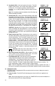
B. Deceleration (DECEL) – Sets the amount of time for the
motor to decelerate from maximum speed to minimum speed.
The DECEL trimpot is factory set for one (1) second, as
shown in Figure 24. For more rapid deceleration time, rotate
the trimpot counterclockwise. For longer deceleration time,
rotate the trimpot clockwise.
Note: Deceleration time will not be shorter than the maximum
coast time of the motor under actual load.
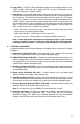
C. Maximum Speed (MAX) – Sets maximum speed of the
motor. The MAX trimpot is factory set for 100% of base motor
speed, as shown in Figure 25. For a higher maximum speed
setting, rotate the trimpot clockwise. For a lower maximum
speed setting, rotate the trimpot counterclockwise.
D. Minimum Speed (MIN) – Sets minimum speed of the motor.
The MIN trimpot is factory set for 0% speed, as shown in
Figure 26. For a higher minimum speed setting, rotate the
trimpot clockwise
13
!
0.5 10
5
1
Seconds
FIGURE 23 – ACCEL
TRIMPOT RANGE
0.5 10
5
1
Seconds
FIGURE 24 – DECEL
TRIMPOT RANGE
5
0 140
95
100
% Base Speed
FIGURE 25 – MAX
TRIMPOT RANGE
030
15
% Base Speed
FIGURE 26 – MIN
TRIMPOT RANGE