
User Guide
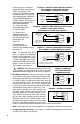
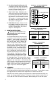


B. Stop (STOP) – The STOP LED will illuminate yellow when the Start/Stop switch is set to
“STOP” position. When AC line is applied, this LED will also be illuminated until the
Start/Stop switch is set to “START” position.
C. Overload (OL) – The OL LED will illuminate red when the control goes into current limit, indi-
cating that the current limit set point has been reached (set by the CL trimpot and the posi-
tion of jumper J2). This LED will remain illuminated if the control times out in TCL (jumper
J3 set to “TCL” position). The control can be reset by either setting the start/stop switch to
“START” position or by disconnecting and reconnecting the AC line. If the overload condi-
tion still exists when the control is restarted or AC line reapplied, the OL LED will illuminate
again. If the OL LED remains illuminated during control operation, a fault condition may
exist. Possible causes for this condition are as follows:
• Motor is overloaded. Check motor current. If the motor is a shunt wound type, the field
may be open or not receiving proper voltage.
• Motor may be defective. Check motor for shorts or grounds.
• CL may be set too low. Check position of CL trimpot and setting of jumper J2.
Note: In some applications, especially those requiring the motor to cycle on and off,
or from one speed to another, or from stop to high speeds, the OL LED may blink,
indicating a transient overload. This may be a normal condition for the application.
X. OPTIONAL ACCESSORIES
Complete instructions and connection diagrams are supplied with all accessories to facilitate
installation.
A. On/Off AC Line Switch (P/N 9341) – Disconnects the AC line. Mounts on the enclosure
cover and is supplied with a switch seal to maintain watertight integrity.
B. FWD-BRK-REV Switch (P/N 9339) – Provides motor reversing and dynamic braking. This
switch is equipped with a center off hesitation mechanism, which assures that the motor is
fully stopped before it can be reversed. Mounts on the enclosure cover and is supplied with
a switch seal to maintain watertight integrity.
C. Run-Stop-Jog Switch (P/N 9340) – Selects speed setting from either main potentiometer
or JOG trimpot. Mounts on the enclosure cover and is supplied with a switch seal to main-
tain watertight integrity.
D. Signal Isolator KBSI-240D (P/N 9431) – Provides isolation from non-isolated signal
sources. Mounts on the inside of the enclosure cover.
E. Auto/Manual Switch (P/N 9377) – When used with the KBSI-240D (P/N 9431), it selects
either an isolated signal from the KBSI-240D or from the main speed potentiometer. Mounts
on the enclosure cover and is supplied with a switch seal to maintain watertight integrity.
F. Anti-Plug Reversing Module APRM-PC (P/N 9378A) – Provides electronic braking and
reversing. Mounts on the inside of the enclosure cover.
Note: For use with this control, the APRM-PC must be Revision A or newer.
G. RFI Filters and Chokes – RFI Filters and Chokes are available to provide suppression for
conducted radio frequency interference (RFI). They comply with the CE Directive
89/336/EEC relating to the EMC Class A Industrial Standard and Class B Residential
Standard. See RFI Filters and Chokes Selection Guide (Publication No. D-321).
15