
User Guide

III. WIRING INSTRUCTIONS
WARNING! Read Safety
Warning, on page 1, before
using this control. Disconnect the AC
line before wiring.
Note: To avoid erratic operation, do not
bundle AC line and motor wires with wires
from signal following, start/stop switch,
inhibit, or any other signal wires. Use
shielded cables on all signal wiring over
12” (30cm). Shield should be Earth
grounded on the control side only. Wire
the control in accordance with the
National Electrical Code requirements
and other codes that may apply to your area. See Figure 3, Table 3 and Table 4, on page 7.
Be sure to properly fuse each conductor that is not at ground potential. Do not fuse neutral
or grounded conductors. See Section VII, on page 13. A separate AC line switch or con-
tactor must be wired as a disconnect so that each ungrounded conductor is opened. An acces-
sory On/Off AC Line Switch (P/N 9341) may be used in lieu of, or in addition to, the Start/Stop
switch. The switch can be wired for single pole or double pole operation, as required.
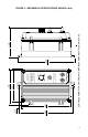
To maintain the watertight integrity of the control, be sure to use suitable watertight connectors
and wiring which are appropriate for the application. Two 7/8” (22.2mm) knockout holes are
provided for standard 1/2” knockout connectors (not supplied) for wiring. A watertight plug is
provided if only one knockout is required.
Warning! Do not wire switches or relays in series with the armature. Armature switching
can cause catastrophic failure of motor and/or control. To avoid erratic operation, do not
bundle AC line and motor wires with potentiometer wires, voltage following wires, Start/Stop
switch wires, inhibit wires, or any other signal wires. Use shielded cables on all signal wiring
over 12” (30cm) long. Shield should be Earth grounded on the control side only.
Warning! Do
not use CON2 for any purpose other than to power the optional Anti-Plug Reversing
Module APRM-PC (P/N 9378A).
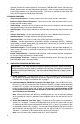
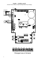
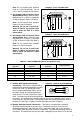
A. AC Line Connection – Wire AC line input to L1 and L2 terminals of TB1 as shown in
Figure 3.
B. Ground Connection – Earth ground the control chassis using the green ground screw that
is provided on the inside of the control to the right side of TB1 as shown in Figure 3.
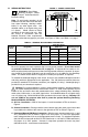
C. Permanent Magnet (PM) Motor Connection – Wire the motor armature leads to A1 (+) and
A2 (-) terminals of TB1 as shown in Figure 3. Be sure jumper J1 is set to the appropriate
motor voltage and that J3 is set to the appropriate motor current. For step-down operation
(230 Volt AC line input with 90 Volt DC SCR rated motor or 130 Volt DC PWM rated motor)
set jumper J1 to “90V” position. However, in step-down operation the motor may have
reduced brush life - consult motor manufacturer.
6
!
!
AC LINE
+
M
-
MOTOR
GROUND
(EARTH)
TB2
L2A2A1 L1
F2F1
TB1
FIGURE 3 – POWER CONNECTION
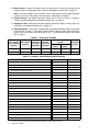
3.5
12
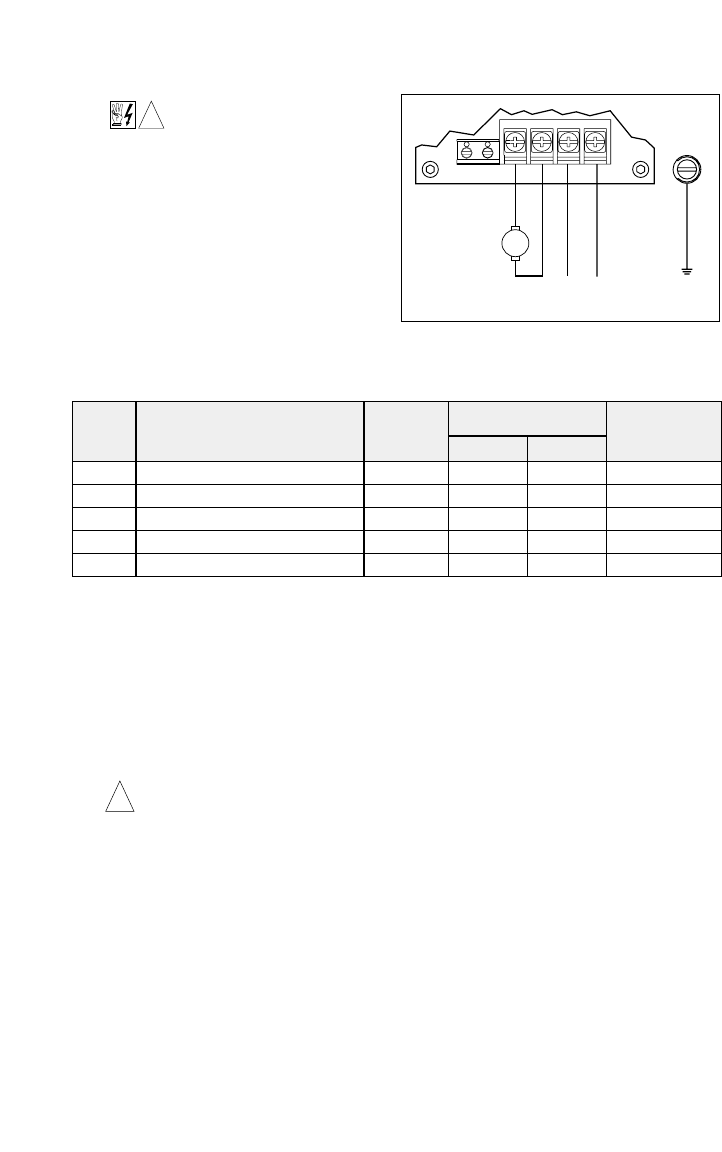
Terminal
Block
TB1
TB1
TB2
TB3
Supply Wire Gauge
(AWG - Cu)
TB4
Designation Connections
Maximum
Tightening Torque
(in-lbs)
L1 & L2
A1 & A2
F1 & F2
T+ & T-
K1 & K2
Minimum Maximum
22
22
24
24
24
12
12
14
14
14
12
3.5
3.5
AC Line Input
Motor Armature
Motor Field (Shunt Wound Motors Only)
Tach-Generator
Run Relay
TABLE 3 – TERMINAL BLOCK WIRING INFORMATION