INSTALLATION AND OPERATING INSTRUCTIONS REGENERATIVE DRIVE MODEL KBRG-213D KB Part No. 8826 VARIABLE SPEED SCR CONTROL DESIGNED FOR SHUNT WOUND and PM DC MOTORS FULL WAVE • 4 QUADRANT See Safety Warning on Page 1 The information contained in this manual is intended to be accurate. However, the manufacturer retains the right to make changes in design which may not be included herein. See Page 1 A COMPLETE LINE OF MOTOR DRIVES © 1998 KB Electronics, Inc.
TABLE OF CONTENTS Section Page i. Safety Warning . . . . . . . . . . . . . . . . . . . . . . . . . . . . . . . . . . . . . . . . . . . . . . . . . . . . . . . . . 1 I. General Information . . . . . . . . . . . . . . . . . . . . . . . . . . . . . . . . . . . . . . . . . . . . . . . . . . . . . 1 II. Operation . . . . . . . . . . . . . . . . . . . . . . . . . . . . . . . . . . . . . . . . . . . . . . . . . . . . . . . . . . . . . 1 III. Setting Selectable Jumpers . . . . . . . . . . . . . . . . . . .
i. SAFETY WARNING! — PLEASE READ CAREFULLY This product should be installed and serviced by a qualified technician, electrician or electrical maintenance person familiar with its operation and the hazards involved.
To understand the concept of a regenerative drive, the operation of an elevator can be used. If one were to enter the elevator on the first floor and press 10, the motor and control would have to lift the elevator against gravity. In this mode, the drive would operate like a conventional speed control which is called “motoring” (the applied load is opposite to the direction of motor rotation).
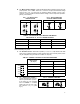
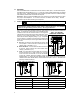
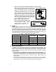
B. J3 – Motor Armature Voltage – Select the desired armature voltage by placing J3 in the proper position, “90" or “180.” Note: For 115 volt AC Line input, the armature voltage must be set to “90.” For 230 input, the armature voltage normally is set for “180.” However, it is also possible to set the armature voltage to “90" for step-down operation. (See fig. 2 and table 4.) FIG. 1 – AC LINE VOLTAGE JUMPER SETTING 115VAC FIG.
IV. MOUNTING. Mount the KBRG-213D on a flat surface free of moisture, metal chips, or corrosive atmosphere. See Mechanical Specifications fig. 7, p. 6. A 5K ohm remote speed potentiometer is provided with each control. Install potentiometer using hardware provided. Be sure to install insulating disk between potentiometer and inside of front panel. Enclosure – When mounting the KBRG-213D in an enclosure, it must be large enough to allow the proper heat dissipation.
5 FIG.
6 FIG.
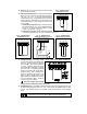
D. Ground – Be sure to ground (earth) control via green screw located on chassis. FIG. 8 – UNIDIRECTIONAL OPERATION (Forward) E. Main Speed Potentiometer – The main speed potenti-15V SIG +15V MIN ometer can be connected in several ways using terminals “S0,” “S1,” “S3.” (A 5K ohm potentiometer is supplied with control. (A 10K potentiometer can also be used.) (Warning! Terminals S0, S1, S2 and S3 are not S3 S2 S1 S0 isolated from AC line.) Note: Jumper J5 must be in the “15V” position. i.
i. Regen to stop using terminals RB1 and RB2 on terminal block TB3: When a contact closure is made, the control will use FIG. 13 – REGEN TO STOP regenerative braking to bring the motor to a rapid stop. In the forward direction the rate of braking can be slowed by increasing the setting of the reverse acceleration trimpot (REV ACC). The rate of braking can be made faster by decreasing the setting of the REV ACC trimpot to its full CCW position.
The FWD and REV ACCEL trimpots are factory adjusted to approximately 1 second. The acceleration times are adjustable over a range of 0.1 to 15 seconds. See fig. 15 for graphical representation of ACCEL. Note: The FWD and REV CL trimpots may override the rapid accel and decel settings. Note: A 4-quadrant ACCEL/DECEL accessory module is available as an option. It provides separate control of FORWARD acceleration and deceleration and REVERSE acceleration and deceleration. (KB P/N 8803) FIG.
The DB trimpot also determines the amount of delay that will occur before regeneration starts. Regeneration occurs when the applied load torque is in the same direction as the motor rotation. To readjust the DB to factory setting: i. Set Main Speed pot to zero speed position. ii. Set DB trimpot to full CCW position. iii. Adjust DB trimpot CW until motor hum is eliminated. (See fig. 17, p. 9 for graphic illustration of the DB trimpot.
IX.
X – LIMITED WARRANTY For a period of 18 months from date of original purchase, KB will repair or replace without charge devices which our examination proves to be defective in material or workmanship. This warranty is valid if the unit has not been tampered with by unauthorized persons, misused, abused, or improperly installed and has been used in accordance with the instructions and/or ratings supplied.