
User Guide


8
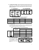
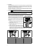
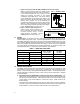
FIG. 13 – REGEN TO STOP
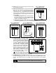
FIG. 14 – COAST TO STOP
i. Regen to stop using terminals RB1 and RB2 on terminal block TB3:
When a contact closure is made, the control will use
regenerative braking to bring the motor to a rapid stop.
In the forward direction the rate of braking can be
slowed by increasing the setting of the reverse
acceleration trimpot (REV ACC). The rate of braking
can be made faster by decreasing the setting of the
REV ACC trimpot to its full CCW position. More rapid
braking, when required, can be accomplished by
increasing the setting of the reverse current limit trimpot
(REV CL). Note: Increasing the CL beyond 200% of the
motor current rating can lead to premature motor failure.
Use an isolated contact as shown in fig. 13.
ii. Inhibit – Coast to Stop using Conn 1:
When a contact closure is made on the
Conn 1 terminals, the control will cause
the motor to coast to a stop. A 2-wire
mating connector is supplied. Use an
isolated contact as shown in fig 14.
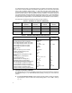
VI. FUSING.
Armature Fuse – An armature fuse (F1) rated 12A is provided with a rating equal to the
maximum RMS rating of the control. It is recommended that the correct size armature fuse
be installed, depending on the rating of the motor and form factor (RMS/AVG current). Fuse
type should be Littlefuse 326 ceramic or Buss ABC, or equivalent. A fuse chart is presented
below which suggests appropriate armature fuse ratings. However, the specific application
may require larger fuse ratings based on ambient temperature, CL set point and duty cycle
of operation (see table 7). Fuses may be purchased from your distributor.
TABLE 7 – ARMATURE FUSE CHART
Motor Horsepower
Approx. DC Motor
Current Amps
Fuse Rating
(AC Amps)
90VDC 180VDC
1/8 1/4 1.3 2
1/6 1/3 1.7 2
1/4 1/2 2.5 4
1/3 3/4 3.3 5
1/2 1 5.0 8
3/4 1 7.5 12
VII. TRIMPOT ADJUSTMENTS.
The KBRG contains trimpots which have been factory adjusted for most applications. See
specifications for factory settings. (Note: fig. 6 p. 5 presents the various trimpots with their
location. They are shown in the approximate adjustment position.) Some applications may
require readjustment of trimpots in order to tailor control to exact requirements. Readjust
trimpots as follows:
A. Forward Acceleration (FWD ACCEL) and Reverse Acceleration (REV ACCEL) – The
FWD ACCEL trimpot determines the amount of time it takes the control voltage to reach
full output in the forward direction. It also determines the amount of time it takes for the
control voltage, in the reverse direction, to reach zero output. (FWD ACCEL is the
Reverse Decel.)
The REV ACCEL trimpot determines the amount of time it takes the control voltage to
reach full output in the reverse direction and the time it takes for the control voltage, in the
forward direction, to reach zero output. (REV ACCEL is the Forward Decel.)