
User Guide

10
The DB trimpot also determines the amount of delay that will occur before regeneration starts.
Regeneration occurs when the applied load torque is in the same direction as the motor
rotation.
To readjust the DB to factory setting:
i. Set Main Speed pot to zero speed position.
ii. Set DB trimpot to full CCW position.
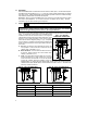
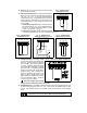
iii. Adjust DB trimpot CW until motor hum is eliminated. (See fig. 17, p. 9 for graphic
illustration of the DB trimpot.) Note: If the deadband trimpot is set too low (CCW
direction), the motor may oscillate between forward and reverse. Adjust deadband
trimpot CW until the instability disappears. (Oscillation may also occur due to STAB
trimpot setting. See sec. VII, G.)
D. Current Limit (FWD CL) and Reverse Current Limit (REV CL) Trimpots – These
trimpots are used to set the maximum amount of DC current that the motor can draw in
both the forward and reverse directions. The amount of DC current determines the
amount of maximum motor torque. They are factory set at 150% of the current
established by the jumper J2 setting.
Readjust the CL trimpot as follows:
i. Turn CL trimpot to MIN (CCW) position. Be sure jumper J2 is in the proper position
approximately equal to the motor DC ampere rating.
ii. Wire in a DC ammeter in series with armature lead. Lock shaft of motor.
iii. Apply power. Rotate CL trimpot quickly until desired CL setting is reached (factory
setting is 1.5 times rated motor current). Be sure control is in forward direction for
FWD CL trimpot adjustment and likewise with REV CL.
Warning! Do not leave motor shaft locked for more than 2 – 3 seconds to
prevent motor damage.
Caution! Adjusting the CL above 150% of motor rating can cause overheating
and demagnetization of some PM motors. Consult motor manufacturer.
E. IR Compensation (IR Comp) – The IR Comp is used to stabilize motor speed under
varying loads.
Readjust the IR Comp trimpot as follows:
i. Run motor at approximately 30 – 50% of rated speed under no load and measure
actual speed.
ii. Load motor to rated current. Rotate IR Comp trimpot so that loaded speed is the
same as the unloaded speed measured in (i).
Control is now compensated so that minimal speed change will occur over a wide
range of motor load. Note: Too much IR Comp will cause unstable (oscillatory)
operation.
F. Maximum Speed (MAX) – The MAX trimpot is used to set the maximum output voltage
of the control which, in turn, sets the maximum speed of the motor.
Adjust the MAX trimpot as follows:
i. Rotate Main Speed potentiometer to full speed (CW).
ii. Adjust MAX trimpot to desired maximum motor speed.
Note: Do not exceed maximum rated RPM of motor since unstable operation may
result.
G. Stability Trimpot (STAB) – This trimpot determines the dynamic response of the control.
The factory setting is approximately 50% of full rotation. The setting may be increased
if a faster response is required. Note: If response is made too fast, unstable operation
may result.
VIII. FUNCTION INDICATOR LAMP.
LED 1 Power On (PWR ON) indicates that the drive is energized with the AC line.