
User Guide

3
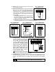
B. J3 – Motor Armature Voltage – Select the desired armature voltage by placing J3 in the
proper position, “90" or “180.” Note: For 115 volt AC Line input, the armature voltage
must be set to “90.” For 230 input, the armature voltage normally is set for “180.”
However, it is also possible to set the armature voltage to “90" for step-down operation.
(See fig. 2 and table 4.)
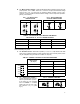
FIG. 1 – AC LINE VOLTAGE
JUMPER SETTING
FIG. 2 – MOTOR ARMATURE
VOLTAGE JUMPER SETTING
115VAC 230VAC 90VDC 180VDC
TABLE 4 – RELATIONSHIP of AC LINE INPUT AND MOTOR
VOLTAGE with J1, J2 and J3 JUMPER POSITION
AC INPUT VOLTAGE J1, J2 POSITION J3 POSITION MOTOR VOLTAGE
115 115 90 90
230 230 180 180
230 230 90* 90*
*A 90VDC motor can be used with a 230VAC line. However, speed range may be reduced and
motor overheating may result.
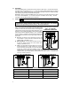
C. J4 – Armature Current – Select the J4 position (1.7, 2.5, 3.3, 5, 7.5) closest to the rated
motor current. (Note the maximum output current is set to 150% of the J4 position, which
may be readjusted using the FWD CL and REV CL trimpots.)
TABLE 5 – JUMPER J4 POSITION vs MOTOR HORSEPOWER
Jumper J4 Position
Motor Current
(DC Amps)
Motor Horsepower
90VDC 180VDC
5.0A
2.5A
1.7A
3.3A
7.5A
J4
7.5A 3/4 1
5.0A 1/2 1
3.3A 1/3 3/4
2.5A 1/4 1/2
1.7A 1/6 1/3
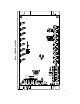
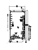
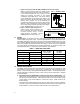
D. J5 – Analog Input Voltage –
Jumper J5 is set to the “15V” po-
sition for potentiometer operation.
If the control is to be operated
from an isolated 0 – ±10VDC
signal, set J5 to the “10V” posi-
tion. (See sec. V, F, p. 7.) (See
fig. 3.)
FIG. 3 – JUMPER J5 SETTING
Potentiometer Operation Signal Following