
User Guide

4
Warning! Read Safety Warning before attempting to use this
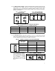
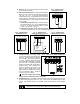
FIG. 4 – AC LINE AND
ARMATURE CONNECTION
IV. MOUNTING.
Mount the KBRG-213D on a flat surface free of moisture, metal chips, or corrosive atmosphere.
See Mechanical Specifications fig. 7, p. 6. A 5K ohm remote speed potentiometer is provided
with each control. Install potentiometer using hardware provided. Be sure to install insulating
disk between potentiometer and inside of front panel.
Enclosure – When mounting the KBRG-213D in an enclosure, it must be large enough to allow
the proper heat dissipation. A 12"12"24" enclosure is suitable at full rating. Smaller
enclosures may be used if full rating is not required.
V. WIRING.
Warning! To avoid erratic operation do not bundle AC Line and motor wires with
potentiometer, voltage following, enable, inhibit or other signal wiring. Use shielded
cables on all signal wiring over 12" (30 cm) – Do not ground shield.
Wire control in accordance with National Electric Code require-ments and other local codes that
apply. A “normal blo” 15 amp fuse or circuit breaker should
be used on each AC line conductor which is not at ground
potential (do not fuse neutral or grounded conductors). (See
section VI, p. 8 for fuse information.) Wire control in accor-
dance with connection diagram (see fig. 6, p. 5). A separate
AC Line switch or contactor must be wired as a disconnect
switch so that contacts open each ungrounded conductor of
the control.
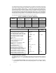
A. AC Line – Connect AC Line to terminals L1 and L2. (Be
sure jumpers J1 and J2 are set to match the AC Line
voltage used.) (See table 4, p. 3.)
B. Motor Armature – Connect motor armature to terminal
A1 and A2. (Be sure jumper J3 is set to match motor
voltage.) (See table 4, p. 3.)
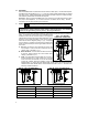
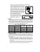
C. Field – [For Shunt Wound motors only. Do not use F1
and F2 terminals for any other motor type.] Connect
motor shunt field to terminals F1 and F2 for 90VDC
motors with 100VDC fields and 180VDC motors with
200VDC fields. For motors with half voltage fields, 90VDC motors with 50VDC fields and
180VDC motors with 100VDC fields, connect field to terminals F1 and L1. See table 6 for
summary of field connections.
FIG. 5A – FULL VOLTAGE FIELD FIG. 5B – HALF VOLTAGE FIELD
TABLE 6 – FIELD CONNECTIONS (Shunt Wound Motors Only)
MOTOR VOLTAGE FIELD VOLTAGE (VDC) FIELD CONNECTION
90 100 F1, F2
90 50 F1, L1
180 200 F1, F2
180 100 F1, L1