
User Guide

“The Right Control for Your Application.”
12095 NW 39 Street, Coral Springs, FL 33065-2516
KB Electronics, Inc. Telephone: 954-346-4900; Fax: 954-346-3377
.%9)0XOWL6SHHG%RDUG,QVWDOODWLRQ:LULQJDQG2SHUDWLQJ,QVWUXFWLRQV
(A42136) - Rev. B00 - 11/02/2004 - Z3269B00 Page 2 of 4
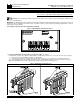
2 Preparing the KBVF Prior to Installing the MSB - See Figure 3.
Remove and discard the jumpers that are installed on J1 (50/60Hz) and CON2 (F-S-R) on the KBVF.
Figure 3 - Preparing the KBVF Prior to Installing the MSB
Before After
PWR
ST
PWR
ST
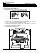
3 Installing and Wiring the MSB - See Figure 4.
3.1 Insert the two 6-32 X ½" screws (provided) through the mounting holes on the MSB and align them with the threaded mounting
holes on the side of the heat sink of the KBVF (located on the side nearest the trimpots).
3.2 Using the flat blade (or Phillips) screwdriver, gently tighten the two screws to secure the MSB to the heat sink (8 in-lbs max.). Do
not overtighten.
3.3 Install the connector with green/black/white wires onto J1 (50/60Hz).
3.4 Install the connector with red/black/white wires onto CON2 (F-S-R).
3.5 Install the terminal with orange wire onto Terminal "P2".
Figure 4 - Installing and Wiring the MSB
ST
PWR
230V 115V