
User Guide
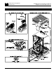


TABLE 1 – GENERAL PERFORMANCE SPECIFICATIONS
II. INSTALLATION INSTRUCTIONS: Mounting the SIMG onto the KBMG
See figure 3 on page 7. Note: This figure is also supplied as a separate drawing.
Warning! Make sure all power is disconnected from the KBMG before
proceeding
.
A. Removing the KBMG Finger-Safe Cover
If a finger-safe cover is not installed on the KBMG, proceed to section IIC (Modifying
the KBMG Finger-Safe cover). If a finger-safe cover is installed on the KBMG,
remove the two (2) socket head 5-40 X 5/16” screws located at the rear of the KBMG
using the supplied 3/32” hex key. Also, remove the two (2) 6-32 X 1-3/4” screws
located on either side of terminal block TB1. See figure 4 on page 8.
6
—
±5 to ±25
MAX Trimpot Range (with 10V DC Input) (% Speed)
Parameter Specification Factory Setting
Voltage Following Input Range (V DC) -10 to +10
Potentiometer Operation (kΩ) 5 —
OFFSET Trimpot Range (with 0V DC Input) (% Speed) ± 50 0
+15V DC and -15V DC Power Supply Max. Current Rating (mA DC)
0 – 110 100
25
—
Forward, Reverse, and Enable Input Switch Types
Dry Contact or
Open Collector
Input/Output Linearity (%) 0.1
—
Thermal Drift (mV/ ºC) 0.4 —
Ambient Operating Temperature Range (ºC) 0 – 50
—
!