User Guide
Manuals
Brands
Kb Electronics Manuals
Other
SIMG
1
2
3
4
5
6
7
8
9
10
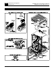
FIGURE 1
–
CONTROL LA
YOUT
(Illustrates Factory
Setting
of Jumpers
and Approximate Trimpot Settings)
3
TACH
CON3
T1(-)
T2(+)
PWR
TB1
L1
COM
EN
SIG
-15V
+15V
L2
J1
ENABLE
A90
T7
A180
T50
F-
CON2
F+
1.7A
F-
OFFSET
2.5
5.0
7.5
10A
MAX
F+
F+
F-
M2
RACC
MAX
FCL
IR
RCL
FACC
M1
DB
RESP
SIMG BIPOLAR SIGNAL ISOLA
T
OR
1
...
...
5
6
7
8
9
...
...
26