SERVICE MANUAL TOP-SIDETM COOKER manufactured years 1998 - 2004 Keating Of Chicago, Inc. 1-800-KEATING www.keatingofchicago.
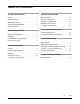
TABLE OF CONTENTS SECTION I INTRODUCTION SECTION IV MAINTENANCE General . . . . . . . . . . . . . . . . . . . . . . . . . . . . . . . . . .1 Warranty Repairs . . . . . . . . . . . . . . . . . . . . . . . . . . .3 Standard Features . . . . . . . . . . . . . . . . . . . . . . . . . .1 Preventive Maintenance . . . . . . . . . . . . . . . . . . . .3-4 Standard Accessories . . . . . . . . . . . . . . . . . . . . . . .1 Installing a Cooking Sheet . . . . . . . . . . . . . . . . . . . .
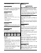
NOTICE: This operating, installation, and service manual should be given to the user. The operator of the griddle should be familiar with the functions and operation of the griddle. This manual must be kept in a prominent, easily reachable location near the griddle. Notice: Keating of Chicago, Inc. (manufacturer) reserves the right to change specifications at any time. FOR YOUR SAFETY DO NOT STORE OR USE GASOLINE OR OTHER FLAMMABLE VAPORS OR LIQUIDS IN THE VICINITY OF THIS OR ANY OTHER APPLIANCE.
I INTRODUCTION SAFETY PRECAUTIONS WARNING GENERAL THIS SYMBOL WARNS YOU THAT SERIOUS BURNS OR OTHER INJURIES MAY RESULT IF SAFETY INSTRUCTIONS ARE NOT FOLLOWED. Keating Top-SideTM Cookers are designed to give maximum production efficiency, delivering high quality food products. The following design features are incorporated into Keating Top-SideTM Cookers.
ELECTRICAL CONNECTION Each Keating Top-SideTM Cooking head is equipped with a 9' (2.74m) neoprene covered, 12 gauge 4mm(2), three wire with ground electrical cord. No plug is provided. Each cooking head is rated 4000W, 18 amps, single phase at 220 Volts (4.37kW, 19 amps, single phase at 230 Volts) and is designed to be connected to its own 208-240V single phase electrical supply.
WARNING THE COOKING HEAD WILL BE HOT. USE PROPER CARE WHEN CLEANING THE COOKING SHEETS. End of day cleaning: Before the griddle is turned off for the day, the cooking sheets should be cleaned as described below. Wear heat resistant gloves for maximum safety during the entire cleaning procedure. NEVER USE ICE TO COOL THE MIRACLEAN® SURFACE AS IT MAY WARP THE MIRACLEAN® SURFACE. USE ONLY KEATING SUPPLIED CLEANING TOOLS AND KLENZER. USE ONLY A KEATING STEEL SPATULA.
PREVENTIVE MAINTENANCE CHART TIME FRAME OPERATOR/OWNER Cooking sheets should never: SECTION Daily Clean all cooking sheets. Clean all MIRACLEAN®. cooking surfaces. III Be folded or creased. Be touched with sharp objects. Come in contact with griddle scrapers or abrasive pads. Be placed under other equipment or objects. Cooking sheets should always: Weekly Monthly* Yearly* III Clean all surfaces of Top-SideTM Cooker. Verify thermostat settings Review cooking procedures.
5. Do not turn the support pin in either direction. V SERVICE DIAGNOSIS 6. To reattach the cooking head to the ram lift arm, raise cooking head completely and replace cooking head support pin. Insert a new stainless steel cotter pin to secure support pin, holding support pin to keep it from spinning. A properly adjusted Keating Top-SideTM Cooker, with no load, will cycle “ON” approximately every 51/2 to 61/2 minutes.
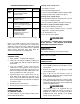
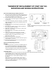
THERMOSTAT REPLACEMENT KIT (PART #057138) MOUNTING AND WIRING INSTRUCTIONS New Thermostat Mounting and Wiring Instructions 1. After removing the old thermostat, drill four larger holes for mounting new housing (See Figure A). After drilling holes, remove any metal filings from inside the unit. 2. Feed the female ends of the four new wires from the inside to the outside of the unit through the old thermostat’s mounting hole. 3.
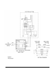
Part # 056840 Figure C: Wiring Diagram 7
VI EXPLODED VIEW & PARTS LIST ORDERING PARTS Parts may be ordered by part number by calling 1-800-KEATING or your local service company. You may also order online at Keating’s part store, www.keatingofchicago.com Refer to the Keating Top-Side™ Cooker Limited Warranty for complete service and ordering information. The model/serial plate for each cooking head is located on the the control panel assembly. The serial and model numbers are necessary when ordering.
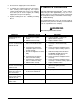
TOP-SIDETM COOKING HEAD FOR MANUFACTURED YEARS 4/99 - 2004 Figure 6-1 PART ITEM DESCRIPTION 1 2 3 4 5 6 7 9 10 11 12 13 14 15 16 17 18 19 20 21 22 23 24 25 26 27 28 29 30 31 32 33 34 35 36 37 38 39 40 41 42 43 44 45 46 47 48 49 50 51 THERMOSTAT TEMPERATURE PROBE KIT COOKING HEAD (COMPLETE) STOP CLEVIS PIN, S/S SWIVEL BRACKET WIRE SLEEVE (INCL.
TOP-SIDETM COOKER CONTROL PANEL ITEM 1 2 3 4 5 6 7 8 9 10 11 12 13 14 DESCRIPTION THERMOSTAT THERMOSTAT KNOB THERMOSTAT DIAL PLATE HI-LIMIT CONTROL HI-LIMIT MOUNTING BRACKET CONTACTOR, 50A, 3-POLE ROCKER SWITCH, LIGHTED, ON/OFF INSTRUCTION PLATE ON/OFF SWITCH PLATE INDICATING LIGHT, ELEMENT ON, RED 250V INSTRUCTION PLATE ELEMENT ON LIGHT PLATE TERMINAL BLOCK 3 POLE COVER (without SERIAL PLATE) CORD, WITHOUT PLUG, 12/3 SJO PANEL TRAY QTY.
VII WIRING DIAGRAM TOP-SIDETM COOKER WIRING DIAGRAMS 11
SERVICE INFORMATION If you have a service related question call 1-800-KEATING. Please state the nature of the call; it will ensure speaking with the appropriate person. Have your serial and model number available when ordering parts. KEATING OF CHICAGO, INC. 8901 West 50th Street, McCook, Illinois 60525-6001 Phone: (708) 246-3000 FAX: (708) 246-3100 Toll Free 1-800-KEATING (In U.S. and Canada) www.keatingofchicago.com *As continuous product improvement occurs, specifications may be changed without notice.