SERVICE MANUAL TOP-SIDE COOKER ™ 325 325 35 T2 T3 TO AL CV °F PUSH TO SET DI RA T E SH I F T WATLOW ON ELEMENT °C LOAD LOAD ON PUSH TO SET CA LI B DI RA T E S H I F T AL CV °F °C OFF 0 250 250 ON LI B 35 400 400 WATLOW T1 SET CA 0 375 375 TO ELEMENT 30 1-800-KEATING 0 275 0 275 30 ON OFF Keating of Chicago, Inc. 1-800-KEATING www.keatingofchicago.
TABLE OF CONTENTS SECTION I INTRODUCTION SECTION IV MAINTENANCE General . . . . . . . . . . . . . . . . . . . . . . . . . . . . . . . . . .1 Warranty Repairs . . . . . . . . . . . . . . . . . . . . . . . . . . .3 Standard Accessories . . . . . . . . . . . . . . . . . . . . . . .1 Installing a Cooking Sheet . . . . . . . . . . . . . . . . . . . .4 Preventive Maintenance . . . . . . . . . . . . . . . . . . . .3-4 Standard Features . . . . . . . . . . . . . . . . . . . . . . . . . .
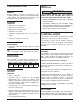
i NOTICE: This operating, installation, and service manual should be given to the user. The operator of the TopSide Cooker™ should be familiar with its functions and operation. This manual must be kept in a prominent, easily reachable location near the Top-Side Cooker™. i NOTICE: Keating of Chicago, Inc. (manufacturer) reserves the right to change specifications at any time. WARNING WARNING DO NOT STORE OR USE GASOLINE OR OTHER FLAMMABLE VAPORS OR LIQUIDS IN THE VICINITY OF THIS OR ANY OTHER APPLIANCE.
I INTRODUCTION SAFETY PRECAUTIONS GENERAL Keating Top-Side™ Cookers are designed to give maximum production efficiency, delivering high quality food products. The following design features are incorporated into Keating Top-Side™ Cookers. WARNING THIS SYMBOL WARNS YOU THAT SERIOUS BURNS OR OTHER INJURIES MAY RESULT IF SAFETY INSTRUCTIONS ARE NOT FOLLOWED.
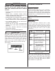
Clockwise movement of the knob will decrease the spacing; counter clockwise movement will increase the spacing. Each turn of the adjusting knob represents 1/8'' (approximately 3mm) movement. ELECTRICAL CONNECTION Each Keating Top-Side™ Cooking head is equipped with a 9' (2.74m) neoprene covered, 12 gauge 4mm(2), three wire with ground electrical cord. Each cooking head is rated 4000W, 18 amps, single phase at 220 Volts and is designed to be connected to its own 208240V single phase electrical supply.
IV MAINTENANCE WARNING BECAUSE OF THE SUPERIOR MIRACLEAN® SURFACE, THE ONLY TOOLS YOU WILL EVER NEED TO CLEAN THE TOP-SIDE™ COOKING HEAD ARE A DAMP SOFT COTTON CLOTH AND A KEATING SCRAPER. l l l l l l l WARRANTY REPAIRS Keating’s warranty begins with the date of installation. In the event your Keating Top-Side™ Cooker needs repair under warranty other than routine maintenance or cleaning you are requested to contact KEATING OF CHICAGO, INC. at 1-800-KEATING before calling a local service company.
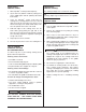
INSTALLING A COOKING SHEET LEVELING OF COOKING HEAD(S) 2. Lay the 20'' x 24'' (508mm x 610mm) cooking sheet on the griddle plate with 20'' (508mm) dimension front to back. ¥ NOTE: For best results, level griddle before checking. Adjust legs or stand casters to level griddle. 1. Raise Top-Side™ Cooking head completely. The cooking head(s) were leveled at the factory. REMOVAL OF COOKING HEAD 3.
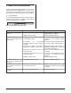
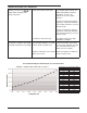
V SERVICE DIAGNOSIS A properly adjusted Keating Top-Side™ Cooker, with no load, will cycle “ON” approximately every 51/2 to 61/2 minutes. Each cycle will last 40 seconds, ensuring that the temperature setting is held within a narrow range. A. Trouble-Shooting The following diagnosis is only to be used as a guide to qualified service personnel. Keating recommends that you use a qualified service company. WARNING Disconnect power before servicing.
TROUBLESHOOTING THE THERMOSTAT Temperature reading is incorrect, showing a sensor error, or LOAD LED is switching at the wrong temperature. • Sensor or controller may be bad. Sensor connections may be bad. Place a jumper wire across the thermocouple input terminals. The display should indicate ambient temperature. If it does, the controller is ok. If not, replace controller. Decrease set point below ambient temperature, LOAD LED should be off for heating controllers. If it is, the controller is OK.
VI EXPLODED VIEW & PARTS LIST ORDERING PARTS Parts may be ordered by part number by calling 1-800-KEATING or your local service company. You may also order online at Keating’s part store, www.keatingofchicago.com. Refer to the Keating Top-Side™ Cooker Limited Warranty for complete service and ordering information. The model/serial plate for each cooking head is located on the the control panel assembly. The serial and model numbers are necessary when ordering.
TOP-SIDE™ COOKING HEAD – MANUAL & AUTO-LIFT Figure 6-1 ITEM 1 2 3 4 5 6 7 9 10 11 12 13 14 15 16 17 18 19 20 21 22 23 24 25 26 27 28 29 30 31 32 33 34 35 36 37 38 39 40 41 42 43 44 45 46 47 48 49 50 51 DESCRIPTION THERMOSTAT TEMPERATURE PROBE KIT COOKING HEAD (COMPLETE) STOP CLEVIS PIN, S/S SWIVEL BRACKET WIRE SLEEVE (INCL.
AUTO-LIFT TOP-SIDE™ COOKER Figure 6-2 ITEM 1 2 3 4 5 6 7 8 9 DESCRIPTION TOP-SIDE COOKER WELD. AUTO NEW ARM AUTO TOP SIDE A0-2 ACTUATOR MTG. ACTUATOR AUTO TOPSIDE COOKER 24V TOP-SIDE CONDUIT SUPPORT TOP-SIDE COOKER LIFT ARM ROD TOP-SIDE COOKER HEAD W/ CONDUIT AND CONTROL PANEL 3 /8" - 2 1/2" CLEVIS PIN PIN HAIR 5/16" - 3/8" : 0.72 WIRE TOP-SIDE COOKER LIFT ARM ROD 9 QTY.
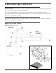
INSTRUCTIONS FOR MICROSWITCH ADJUSTMENT AUTO-LIFT TOP-SIDE™ ACTUATOR Figure 6-3 and the stroke should stop retracting before it reaches its mechanical stop. This movement is controlled by the bottom micro switch. 1. Remove the limit switch black plastic cover on the actuator. 2. Turn on the power on unit and push the T1, T2 or T3 button on the timer. The actuator will extend the stroke and lower head. The motor must stop and the stroke should stop extending before it reaches its mechanical stop.
TOP-SIDE™ COOKER CONTROL PANEL Figure 6-4 ITEM 1 2 3 4 5 6 7 8 9 10 11 12 13 14 DESCRIPTION THERMOSTAT THERMOSTAT REPLACEMENT KIT HI-LIMIT CONTROL HI-LIMIT MOUNTING BRACKET CONTACTOR, 50A, 3 POLE ROCKER SWITCH, LIGHTED, ON/OFF INSTRUCTION PLATE ON/OFF SWITCH PLATE INDICATING LIGHT, ELEMENT ON, RED INSTRUCTION PLATE ELEMENT ON LIGHT PLATE TERMINAL BLOCK CORD, WITHOUT PLUG, 12/3 SJO GROUND LUG 1/4" CONDUIT 65" COMPLETE WITH WIRES CONNECTOR 1/2" LIQUID TIGHT 45° CONNECTOR 1/2" LIQUID TIGHT STRAIGHT Top Vi
VII WIRING DIAGRAM TOP-SIDE™ COOKER MANUAL LIFT WIRING DIAGRAM Figure 6-5 LIGHTED ROCKER ON/OFF SWITCH GREEN LIGHT ON TOP OR LIGHTED ROCKER ON/OFF SWITCH GREEN LIGHT ON BOTTOM NOTE: ANGLED TERMINALS OF SWITCH ARE ALWAYS TOWARD CONTROL PANEL BOTTOM.
TOP-SIDE™ COOKER AUTO-LIFT WIRING DIAGRAM Figure 6-6 13
100% 80% 60% 40% 20% 10% AND CONDITIONS KEATING OF CHICAGO, INC., 1-800-KEATING KEATING WWW.KEATINGOFCHICAGO.COM REFILE/warranty 8/07 All repair services under this Limited Warranty must be authorized by Keating or performed at Keating. Authorization may be obtained by calling 1-800-KEATING within the Continental United States, Alaska, Hawaii, Puerto Rico and Canada during normal business hours (7:00 a.m. through 6:00 p.m. Central Time, Monday through Friday).
SERVICE INFORMATION If you have a service related question call 1-800-KEATING. Please state the nature of the call; it will ensure speaking with the appropriate person. Have your serial and model number available when ordering parts. KEATING OF CHICAGO, INC. 8901 W. 50th Street, McCook, Illinois 60525-6001 Phone: (708) 246-3000 FAX: (708) 246-3100 Toll Free 1-800-KEATING (In U.S. and Canada) www.keatingofchicago.com *As continuous product improvement occurs, specifications may be changed without notice.