
Technical Description


RFID-Module Product overview
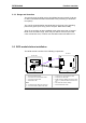
3.1.1 Range and detection
The typical range for RFID card to XE 020/ANT antenna module is 40 mm
for the recommended RI-I02112A-03 RFID card (assuming an aluminium
front panel).
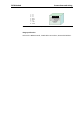
The card is recognised when the RFID LED on the front of the operating
panel turns green (for 3 secs) (refer to chapter “RFID status LED“).
There is no provision to detect multiple cards at the same time. If several
RFID cards are within range, either only one will be detected or this will
cause a detection error, in which case the RFID status LED will turn red.
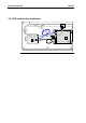
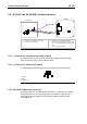
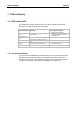
3.2 RFID module before installation
The RFID module consists of the following components:
LED-RT/GN
N1
O N
1 2
XE 020 ANT
XE 020/A
53
57 64
60
1
2
3
4
5
6
7
11
10
9
8
020XE 020/ANT antenna module
1.......Model identification label
2.......Connector for coaxial antenna cable
3.......Connector for LED cable
4.......RFID status LED
Cables
10.....Coaxial antenna cable (max. 300 mm)
11.....Connector cable for RFID status LED
XE 020/A RFID module
5........Connector for coaxial antenna cable
6........Connector for LED cable
7........RJ45 socket for shielded connection cable
(max. 1 m) between RFID module and OP
3xx
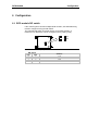
8........DIP switch for address settings
9........Model identification label
RFID module before installation