KeContact P20 Installation manual (for the specialist)
Comments to this manual In this manual you will find warnings against possible dangerous situations. The used symbols apply to the following meanings: WARNING! Indicates a potentially hazardous situation which, if not avoided could result in death or se rious injury. CAUTION! Indicates a potentially hazardous situation which, if not avoided may result in minor or moderate injury. ATTENTION Indicates a situation which, if not avoided could result in property damage.
The device bears the CE mark. The declaration of conformity is being held by KEBA AG. The device meets the ROHS directive (RL 2011/65/EU). The declaration of conformity is being held by KEBA AG. Information on disposal The symbol with the crossedout garbage can points out that electrical and electronic devices including their accessories should not be disposed of in the household garbage.
Contents Contents 1 2 Important information ............................................................................................................. 6 1.1 Safety information .......................................................................................................... 6 1.2 Intended use .................................................................................................................. 8 1.3 About this manual .............................................................
Contents 5.2 Configuring the communication with the electric vehicle PLC>Ethernet (optional)..... 41 5.3 Replacing the fuse ....................................................................................................... 41 5.4 Dimensions .................................................................................................................. 42 5.5 Technical data.............................................................................................................. 43 5.
Important information 1 Important information 1.
Important information ATTENTION Risk of damage! ● Make sure that the charging station is not damaged by improper handling (anchoring, housing cover, socket, inner parts etc.). ● Do not open the connector panel cover in the rain! ● Risk of breaking the plastic housing! Countersunk screws may not be used for the mounting! The included washers must be used. Do not tighten the mounting screws with force. The mounting surface must be completely level (max.
Important information 1.2 Intended use The device is a "charging station" for the indoor and outdoor area at which electrically operated vehicles can be charged (e.g. electric automobiles). The charging station is designed for installation on a wall or in a floormounted column. The respective national regulations must be observed with regard to the installation and connection of the charging station.
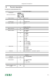
Important information 1.4 Product description Example KCP20ES240030000xxxx Product description Model plate See top on the device Product family KC KeContact Product type P Charge Point Type / Version 20 Type Design versions Basic versions E E…Europe Cable / Socket S S…Socket C…Cable 2 1…Type 1 2…Type 2 S…Shutter 4 1…13A 2…16A 3…20A 4…32A 00 00…no cable 01…4m straight 04…6m straight 99…4m spiraled Electronics 3 0...eseries 1...bseries 2...cseries 3...
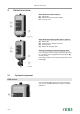
Variant overview 2 Variant overview Base model with socket (Type 2)… [A]…Status LED [B]…Standard socket (variants possible) [C]…Housing cover Base model with charging cable Type 1, Type 2)… [A]…Status LED [B]…Parking bay for charging connector [C]…Housing cover [D]…Bracket for charging cable Storing the charging connector/charging cable… If no charging procedure is being performed, the charg ing connector can be plugged into the parking bay [B] for safe storage.
Variant overview Key switch The key switch [S] is used for authorizing a user. Additional optional equipment ● Network capability ● Switch contact (for control of external additional equipment) ● Enable input for e.g. ripple control receivers, time switches,… (This permits a scheduled (timecontrolled) charging of the vehicle to be realized.
Installation guidelines 3 Installation guidelines 3.1 General criteria for the site selection The charging station was constructed for the indoor and outdoor area. Accordingly it is necessary to ensure the installation conditions and the protection of the device at the installation site. ● Take into account the local electrical installation regulations, fire prevention measures and accident pre vention regulations as well as emergency routes at this site.
Installation guidelines 3.2 Specifications for the electrical connection 3.2.1 General The charging station is set to 10 amps in the delivery state. Set the maximum current using the DIP switches to match the installed circuit line breaker (see Chapter "4.6 DIP switch settings"). The power supply line must be hardwired to an existing house installation and correspond to the nationally applicable legal conditions.
Installation guidelines 3.2.2 Differing requirements for compliance with "Z.E.Ready®" (Renault) ● For the case where the internal switching element (contactor) is no longer able to open, an additional switchoff capability must be realized. This can be realized with the switch contact output X2 (for details, see Chapter "4.5.4 Switch contact output [X2] (excluding eseries)"). ● No 13A charging cables may be used.
Installation guidelines 3.3 Space requirements Space requirement… For device versions with optional cable hanger, addi tional free area y for the charging cable to be used is to be accounted for. If several charging stations are installed adjacent to each other, a distance of at least 200 mm between charging stations must be complied with.
Installation 4 Installation Scope of delivery eseries Others Charging station 1 pieces 1 pieces Cable hanger (for versions with charging cable) 1 pieces 1 pieces Installation manual (for the specialist) 1 pieces 1 pieces User manual (for the end customer) 1 pieces 1 pieces Drilling template 1 pieces 1 pieces Keys for cylinder lock (optional) 3 ST RFID card (optional) 1 pieces [1] Cable gland M32x1.5, black (clamping area 10–21mm) 1 pieces 1 pieces [2] Locknut M32x1.
Installation 4.1 Installation requirements ● Before beginning the installation, the installation guidelines must be observed. ● Contact person onsite (for access to the mains disconnector in the electrical distribution panel board). ● The electrical connection (power supply line) must be prepared. ● Acclimatization For a temperature difference of more than 15°C between transport and installation site, the charging sta tion should be allowed to acclimate unopened for at least two hours.
Installation 4.2 4.2.1 Preparing the housing Removing the housing cover Cover screws… Unscrew the two cover screws [S] on the bottom side of the housing cover. Removing the housing cover… (1) Pull the housing cover down slightly. (2) Slide the housing cover up slightly to unhinge it.
Installation 4.2.2 Removing the connector panel cover Removing the connector panel cover… Unscrew the four screws that mount the connector panel cover and remove the connector panel cover. Take the silica bag out of the terminal panel and dispose of it properly. Information for subsequent assembling Mounting the connector panel cover… Insert the connector panel cover again. Mount the connector panel cover again using the four screws.
Installation 4.3 Preparing the cable insertion There are two possibilities available for the cable insertion: ● Cable insertion from above (surface cable routing) ● Cable insertion from below (flushtype cable routing) Preparations Remove the connector panel cover (see Chapter "4.2.2 Removing the connector panel cover"). Fit the charging station with the required cable glands or dummy screw fittings (if an open cable insertion opening is no longer used).
Installation 4.3.2 Cable insertion from behind flushmounted cable routing A ... Feedthrough/doublemembrane seals M32 (power supply line) B ... Feedthrough/doublemembrane seals M20 (for control line/Ethernet) C ... Feedthrough/doublemembrane seals M20 (for control line/Ethernet) ... Make sure that the connection cable is inserted through the center of the doublemembrane seal to ensure seal tightness.
Installation 4.4 Mounting the charging station Installation materials The included installation material (excluding eseries) is suitable for cement, brick and wood (without an chors). For other surfaces, a suitable method of installation must be selected. Depending on the device model or for special materials, the installation materials must be provided by the customer. A proper installation is absolutely necessary and lies outside of the scope of re sponsibility of the KEBA AG.
Installation Water drainage… The water drainage from the top side to the rear side of the charging station must be ensured. Therefore, ob serve the following: ● Only a vertical installation of the charging station is permitted. ● The charging station must be mounted at an angle of 90° (no inclination is permitted!). Mounting the charging station… Turn the hanger bolts into the anchors until the thread still protrudes approx. 2 cm ('x').
Installation Installation on hollow walls… For installation on hollow walls, at least 2 mounting screws must be secured to a support element of the wall (see figure). Special hollowwall anchors must be used for the other mounting screws. When installing on hollow walls you must ensure that the bearing strength of the construction is sufficient.
Installation 4.5 Electrical connection 4.5.1 Connection overview with opened connector panel cover 1 ... Mains connection phase conductor 1 2 ... Mains connection phase conductor 2 T1 ... Service button LED ... Status LED (internal) 3 ... Mains connection phase conductor 3 X1 ... Enable input N ... Mains connection N wire X2 ... Switch contact output PE ... Mains connection PE wire X3 ... Ethernet2 connection (debug) F1 ... Fuse holder X4 ... Ethernet1 connection (LSA+ terminals) DSW1 ...
Installation 4.5.2 Connecting the power supply line Running the power supply line (surface cable rout ing)… Run the supply line from ABOVE as shown in the figure. [M]… Cable sheathing Running the power supply line (flushtype cable routing)… The power supply cable must be run as shown through the feedthrough/doublemembrane seal [DMS]. Make sure that the doublemembrane seal fits cleanly against the cable sheathing.
Installation Connecting the power supply line… Shorten the connection wires to the appropriate length; these should be kept as short as possible. The PE conductor must be longer than the remain ing conductors! Strip approx.12 mm from the connection wires. Coreend sleeves are recommended for fine stranded wires. Perform the connection of the power supply line [L1], [L2], [L3], [N] and [PE].
Installation Opening the power supply terminal… Using moderate force, press the screwdriver straightly into the terminal until the contact opens completely. The angle of the screwdriver changes while press ing in the terminal. Connecting wires… Insert the stripped connection wire into the power supply terminal. Closing the power supply terminal… Pull the screwdriver out of the terminal completely in order to close the contact. Check that the connection wire is tight.
Installation 4.5.3 Enable input [X1] (excluding eseries) The enable input is equipped for use with a potentialfree contact. Using the enable input, it is possible to control the charging station using external components (e.g. external key switches, ripple control receiver of the energy supplier, house control, time switches, combination lock, photovoltaic system etc.).
Installation 4.5.4 Switch contact output [X2] (excluding eseries) The switch contact output (signal contact) is a potentialfree relay contact and signals a fault for the internal contactor. If the output is used, the corresponding DIP switch setting must be selected. Circuit diagram: Electrical requirements: ● Safety extralow voltage Vcc < 50VAC ● F ≤ 0.5A currentlimiting protective equipment Connection: Connect the wires to the switch contact output (please refer to the chapter "4.5.
Installation Example (supplement to the circuit diagram): The switch contact can be used to switch off the KeContact P20 (disconnect the current) by means of an overriding disconnect solution. Q1 ... Main switch Q2 ... Line circuit breaker + FI circuit breaker Q3 ... Contactor/Relay F1 ... Currentlimiting equipment U1 ... Undervoltage trigger X2 ... Switch contact output 4.5.
Installation 4.5.6 Ethernet1 connection [ETH] (optional) WARNING! Danger from compensation currents on shielding! Compensation currents flowing through shielding in extended systems can lead to damage to the interfaces and hazards when working on the data lines. ● Any measures (such as connecting to a shared distribution board, expanding a TNS network, etc.) should be discussed with the person responsible for building services. The Ethernet1 is designed as terminal block in LSA+® technology.
Installation LSA+® insertion tool Original KRONE insertion tool with solderfree and strippingfree connection of the wires and simultaneous trimming of the residual lengths. Preparing the connection cable… Strip the connection cable approximately 6 cm. Fold back approx. 1 cm of shielded braiding com pletely and wrap it with conductive adhesive textile tape. Connecting the cable… Fix the connecting cable at the point of the wrap around shielding braid in the cable clamp [K].
Installation 4.6 DIP switch settings Changes to the DIP switch settings only become effective after a restart of the charging station! To do this, press the [service button] for 1 second or switch the power supply voltage off/on. DIP switches… The DIP switches are used for the addressing and con figuring the charging station and are located under the connector panel cover.
Installation Only one maximum value can be set with the following DIP switches which is smaller or equal to the operating current according to the type plate: SETTING THE AMPERAGE (DSW1) (*1) Current DIPSwitch Figure D1.6 D1.7 D1.8 10A OFF OFF OFF 13A ON OFF OFF 16A OFF ON OFF 20A ON ON OFF 25A OFF OFF ON 32A ON OFF ON (*1) Preset maximum charging current value for the vehicle (Control Pilot Duty Cycle). OBTAIN IP ADDRESS VIA DHCP (NO ADDRESSING) DSW2.1 to DSW2.
Installation USE FIXED IP ADDRESS DSW2.1 to DSW2.4 / DSW2.5=OFF / DSW2.6=ON Since multiple charging stations are located in a network; an addressing of the charging stations is necessary. Addressing is done using the DIP switches DSW2.1 to DSW2.4. The settable Ethernet addresses start at 10 + DIP switch setting. With the 4bit addressing, the addresses 11 to 26 can be used [192.168 .25.xx]. Example for address "17": DSW2.1 = Address bit 20 (value=1) DSW2.2 = Address bit 21 (value=2) DSW2.
Installation 4.7 Commissioning General commissioning process 1) Remove all residual installation and connection materials from the connection area. 2) Before commissioning, check all screw and terminal connections for tightness! 3) Check whether all unused cable screw connections are properly sealed with blind plugs or dummy screw fittings. 4) Ensure that the voltage of the power supply line is switched on. The status LED should start to slowly flash green after 1520 seconds.
Installation 4.7.2 Safety checks Before the initial use, check the effectiveness of the safety measure(s) of the system according to the nation ally applicable regulations (e.g.:ÖVE/ÖNORM E8001661, DIN VDE 0100600:200806 "Checks,...")! Electrical systems or devices must be checked by the installer of the system or device before their initial op eration. This also applies for the expansion or modification of existing systems or electrical devices.
Installation 4.7.3 Mounting the housing cover Fitting the housing cover… Fit the housing cover at the top and push the cover downwards slightly. Make sure that the housing cover is seated cor rectly at the top in the housing guides. Mounting the housing cover… Then fold the housing cover to the rear. The hous ing cover must glide into the guides without consid erable resistance. Make sure that the housing cover is seated cor rectly on all sides in the housing guide.
Additional technical instructions 5 Additional technical instructions 5.1 Programming RFID user cards (optional) Programming the RFID master card The authorization by an RFID master card is necessary for the programming. The program ming mode can be activated and deactivated using the RFID master card. The first RFID card that is detected by the charging station will automatically be stored as the master card.
Additional technical instructions 5.2 Configuring the communication with the electric vehicle PLC >Ethernet (optional) To grant the vehicle access to the home network or the Internet, the powerline communication between vehi cle and charging station must be configured on both sides using the same password (NMK "Network Mem bership Key"). The standard password is "emobility". We recommend changing this password. The required software ("EV Communication Assistant") incl.
Additional technical instructions 5.
Additional technical instructions 5.5 Technical data Electrical data Cable feed: Surface cable routing or flushtype cable routing Connection crosssection: Minimum crosssection (depending on the cable and the line length): 5 x 2.5 mm² (16A nominal current) 5 x 6.0 mm² (32A nominal current) Supply terminals: Connection line: Fixed (min.max): 0.2 – 16 mm² Flexible (min.max): 0.2 – 16 mm² AWG (min.max): 24 – 6 flexible (min.max) with wire end sleeve without/with plastic sleeve: 0.
Additional technical instructions Interfaces Enable input [X1]: Enable input for external authorization: Connection line: Cross section (min.max): 0.08 – 4 mm² AWG (min.max): 28 – 12 Potentialfree switch contact output [X2]: Safety extralow voltage <50VAC 50/60Hz External current limiting max. 0.5A Connection line: Cross section (min.max): 0.08 – 4 mm² AWG (min.
Additional technical instructions 5.
Index Index C K Cable insertion from above surface cable routing..................................................... 20 Key switch ................................................... 11 Cable insertion from behind flushtype cable routing..................................................... 21 M Charging station with charging cable .......... 10 Mounting the housing cover ........................ 39 Charging station with socket ....................... 10 Commissioning .........................
www.kecontact.