KeContact P20 Installation manual (for the specialist)
Comments to this manual In this manual you will find warnings against possible dangerous situations. The used symbols apply to the following meanings: ! ! WARNING! Indicates a potentially hazardous situation which, if not avoided could result in death or serious injury. CAUTION! Indicates a potentially hazardous situation which, if not avoided may result in minor or moderate injury. CAUTION Indicates a situation which, if not avoided could result in property damage.
The device is designed in accordance with CE-rules. The declaration of conformity is being held by KEBA AG. The device meets the ROHS directive (RL 2011/65/EU). The declaration of conformity is being held by KEBA AG. Information on disposal The symbol with the crossed-out garbage can points out that electrical and electronic devices including their accessories should not be disposed of in the household garbage.
Contents Contents 1 Important information .................................................................................................................... 5 1.1 1.2 1.3 1.4 2 Overview ......................................................................................................................................... 9 2.1 3 3.3 4.2 4.3 4.4 4.5 4.6 4 / 48 Preparing the housing ......................................................................................................... 17 4.1.
Important information 1 Important information 1.
Important information ! WARNING! Pull the charging cable only at the plug and not at the cable out of the connector. Ensure that the charging cable is not mechanically damaged (bent, pinched or run over) and the connection area does not come into contact with heat sources, dirt or water.
Important information 1.2 Intended use KeContact P20 is a "charging station" for the indoor and outdoor area at which electrically operated vehicles can be charged (e.g. electric automobiles). The charging station is designed for installation on a wall or in a floor-mounted column. The respective national regulations must be observed with regard to the installation and connection of the charging station.
Important information 1.4 Product description Example KC-P20-ES240030-000-xxxx Product family - Product type Type / Version - see top of the device KC - P 20 - Type KeContact ChargePoint Type plate Design versions Right 0 0 3 0 - Optional Customer code 2-digit - xx Authentication 0 0…not populated R…RFID K…Key switch Left 0…not populated 8 / 48 0 Options Buttons - 0 Electrics 0…Contactor 1…Contactor 1-phase 1…Type 1 2…Type 2 - 4 Electronics 0...e-series 1...b-series 2.
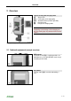
Overview 2 Overview Typical version with charging cable [A]… Status LED [B1]… Parking bay for charging plug [B2]… Standard socket (variants possible) [C]… Housing cover [D]… Hanger for charging cable Note Depending on the design of the charging station, the parking bay may deviate from the form shown. Charging station (application example) 2.
Overview 2.1.1 Additional optional equipment 10 / 48 Network capability Switch contact (for control of external additional equipment) Enable input for e.g. ripple control receivers, time switches,… This permits a scheduled (time-controlled) charging of the vehicle to be realized. PLC (Power Line Communication) according to GreenPhy standard Mounting column 3-phases ZER 1.
Installation guidelines 3 Installation guidelines 3.1 General criteria for the site selection The charging station was constructed for the indoor and outdoor area. Accordingly, it is necessary to ensure the installation conditions and the protection of the device at the installation site. Take into account the local electrical installation regulations, fire prevention measures and accident prevention regulations as well as emergency routes at this site.
Installation guidelines 3.2 Specifications for the electrical connection 3.2.1 General The charging station is set to 10 amps in the delivery state. Set the maximum EVSE current capacity by setting the DIP-switches in coordination with your installed line circuit breaker (see chapter “DIP-switch settings”). The mains supply line must be hardwired to an existing house installation and correspond to the nationally applicable legal conditions.
Installation guidelines 3.2.2 Differing requirements for the fulfillment of „Z.E.-Ready®“ (Renault) For the case where the internal switching element (contactor) is no longer able to open, an additional switch-off capability must be realized. This can be realized with the switch contact output X2 (for details, see chapter "Switch contact output [X2]"). No 13A charging cables may be used.
Installation guidelines 3.3 Space requirements Space requirements For device versions with optional cable hanger, additional and sufficient free area (y) for the charging cable to be used is to be accounted for. If several charging stations are installed adjacent to each other, a distance of at least 200 mm between charging stations must be complied with.
Installation 4 Installation Scope of supply Charging station Cable hanger (for versions with charging cable) Installation manual (for the specialist) User manual (for the end customer) Drilling template Keys for cylinder lock (optional) RFID card (optional) [1] Cable gland M32x1.5 [2] Lock nut M32x1.5 [3] Cable gland M16x1.5 [4] Lock nut M16x1.
Installation Installation requirements Before beginning the installation, the installation guidelines must be observed. Contact person on-site (for access to the mains disconnector in the electrical distribution panel board). The electrical connection (mains supply line) must be prepared. Acclimation: With a temperature difference of more than 15°C between transport and installation site, the charging station should be acclimatized for at least two hours unopened.
Installation 4.1 Preparing the housing 4.1.1 Removing the housing cover Cover screws ► Unscrew the two cover screws [S] on the bottom side of the housing cover. Cover screws Removing the housing cover ► (1) Pull the housing cover out slightly. ► (2) Slide the housing cover up slightly to unhinge it.
Installation 4.1.2 Removing/mounting the connector panel cover Removing the connector panel cover ► Unscrew the four screws with which the connector panel cover is mounted and remove the connector panel cover. Notice Remove the dry bag from the connector panel and dispose it of properly. Removing the connector panel cover Information for reassembly Mounting the connector panel cover ► Insert the connector panel cover again. ► Mount the connector panel cover again using the four screws.
Installation 4.2 Preparing the cable insertion There are two possibilities available for the cable insertion: Cable insertion from above (surface cable routing) Cable insertion from behind (flush-type cable routing) Preparations ► Remove the connector panel cover (see Chapter "Removing/mounting the cable panel cover"). ► Populate the charging station with the required cable glands or seals (if an open cable insertion opening is not used any more).
Installation 4.2.1 Cable insertion from above - surface cable routing Cable insertion openings - top view [A]…Cable gland M32 (mains supply line) [B]…Cable gland M16 (for control line/Ethernet) [C]…Cable gland M16 (for control line/Ethernet) 4.2.
Installation It is important to ensure that the connection cable is inserted through the center of the double membrane seals to ensure the correct sealing of the device. Cable outlet A double flush-mounted box with separating divider for secure separation can be provided for the cable insertion. [A]… mains supply line [B]… control line [C]… Ethernet Flush-mounted box 4.
Installation Marking the holes ► Mark the four holes [1] to [4] using the supplied drilling template and a spirit level. ► Drill the four mounting holes. Information about the drilling template: The drilling template shows the outer contour of the charging station. The four main mounting holes are aligned centered to the slotted holes on the device.
Installation Mounting the charging station ► Turn the hanger bolts into the anchors until the thread still protrudes approx. 2 cm ('x'). ► Use the shims [A] to compensate for any unevenness and to ensure a water drainage behind the device. ► Position and mount the charging station using the supplied washers and nuts.
Installation 4.4 Electrical connection 4.4.
Installation 4.4.2 Connecting the mains supply line Running the mains supply line (surface cable routing) ► Run the mains supply line from ABOVE as shown in the figure. [M]… cable sheathing Running the mains supply line Running the mains supply line (flush-type cable routing) ► The power supply cable must be run as shown through the feedthrough/doublemembrane seal [DMS]. Make sure that the double-membrane seal fits cleanly against the cable sheathing.
Installation Connecting the mains supply line ► Shorten the connection wires to the appropriate length; these should be kept as short as possible. The PE conductor must be longer than the remaining conductors! ► Strip approx.12 mm from the connection wires. Wire end sleeves are recommended for finely stranded wires. ► Perform the connection of the mains supply line [L1], [L2], [L3], [N] and [PE].
Installation Opening the supply terminal ► Push the screwdriver with moderate force straight into the terminal until the wire connector is completely open. During pushing into the supply terminal, the angle of the screwdriver is changing. ATTENTION Risk of breaking the terminal! Do not pry the screwdriver up, down or to the side! Opening the supply terminal Connecting the wire ► Push the stripped connection wire into the supply terminal as shown on the picture.
Installation 4.4.3 Enable input [X1] (except e-series) The enable input is equipped for the use with a potential-free contact. Using the enable input, it is possible to control the charging station using external components (e.g. external key switches, ripple control receiver of the energy supplier, house control, time switches, combination lock, photovoltaic system etc.).
Installation 4.4.4 Switch contact output [X2] (except e-series) The switch contact output (signal contact) is a potential-free relay contact and signals a fault for the internal contactor. If the output is used, the corresponding DIP switch setting must be selected. Circuit diagram: Electrical requirements: - Safety extra-low voltage Vcc < 50VAC - F ≤ 0.
Installation Example (supplement to the circuit diagram): The switch contact can be used to switch off the KeContact P20 (disconnect the current) by means of an overriding disconnect solution. -Q1… Main circuit breaker -Q3… Contactor/Relay -U1… Undervoltage release -Q2… Line circuit breaker + RCD circuit breaker -F1… Current-limiting protective device -X2… Switch contact output 4.4.
Installation 4.4.6 Ethernet1 connection [ETH] (optional) WARNING! ! Danger from compensation currents on shielding! Compensation currents flowing through shielding in extended systems can lead to damage to the interfaces and hazards when working on the data lines. Any measures (such as connecting to a shared distribution board, expanding a TN-S network, etc.) should be discussed with the person responsible for building services. The Ethernet1 is designed as terminal block in LSA+® technology.
Installation LSA+® insertion tool Original KRONE insertion tool with solder-free and stripping-free connection of the wires and simultaneous trimming of the residual lengths. LSA+® insertion tool Preparing the connection cable ► Strip the connection cable approximately 6 cm. ► Fold back approx. 1 cm of shielded braiding completely and wrap it with conductive adhesive textile tape.
Installation 4.5 DIP-switch settings Changes in the DIP-switch settings will take effect once the charging station has been restarted! To do this press the [Service button] for 1 second or switch the power supply voltage off/on. DIP-switches The DIP-switches are used for the addressing and configuring the charging station and are located under the connector panel cover.
Installation Function PHASES / ONLY FOR LOAD MANAGEMENT MODE DSW1.3 to DSW1.5 DIP-switch Figure ON= only 1 phase Supply (phases) D1.3 Phase assignment (*) D1.4 D1.5 OFF OFF ON OFF Phase L2 at terminal 1 connected OFF ON Phase L3 at terminal 1 connected ON ON OFF= all 3 Phases Figure Phase L1 at terminal 1 connected (*) Comments: For load distribution, with 1-phase operating mode, any phase (L1, L2 or L3) of the mains supply line can be connected to the connection terminal 1.
Installation Only one maximum value can be set with the following DIP switches which is smaller or equal to the operating current according to the type plate: SETTING THE AMPERAGE (DSW1) (*1) Current D1.6 D1.7 D1.8 10A OFF OFF OFF 13A ON OFF OFF 16A OFF ON OFF 20A ON ON OFF 25A OFF OFF ON 32A ON OFF ON Figure (*1) Preadjusted maximum current value for the EV charger (control pilot duty cycle). STANDARD MODE + DHCP (NO ADDRESSING) DSW2.1 to DSW2.4=OFF / DSW2.
Installation STANDARD MODE + ADDRESSING DSW2.6=ON The charging procedure in STANDARD mode is carried out automatically by the charging station without higher-ranking control system. The charging station has the static IP address: [192.168.25.xx] Example: address 17 Set the desired IP address with the DIPswitches DSW2.1 to DSW2.4 (see “Addressing”). LOAD MANAGEMENT MODE + ADDRESSING DSW2.6=OFF The charging procedure in LOAD MANAGEMENT mode is controlled by a higherranking load management system.
Installation Function Commissioning mode activate COMMISSIONING MODE (DSW2.8) DIP-switch D2.8 Figure ON=yes Set D2.1 to D2.7 to OFF! 4.6 Commissioning General commissioning process 1. Remove all residual installation and connection materials from the connection area. 2. Before commissioning, check all screw and terminal connections for firm seating! 3. Check whether all unused cable glands are properly sealed with blind plugs or dummy screw fittings. 4.
Installation 4.6.1 Commissioning mode/self test General The charging station can be placed into a commissioning mode for supporting the initial system test. During this, a self test of the device is performed (interlocking, contactor activation, current measurement, etc.) and the result is displayed. After successful test without connected vehicle, the contactor is switched for limited time in order to facilitate the initial tests. A normal charging procedure is not possible in commissioning mode.
Installation 4.6.2 Safety checks Before the initial use, check the effectiveness of the safety measure(s) of the system according to the nationally applicable regulations (e.g.:ÖVE/ÖNORM E8001-6-61, DIN VDE 0100-600:2008-06 "Checks,...")! Electrical systems or devices must be checked by the installer of the system or device before their initial operation. This also applies for the expansion or modification of existing systems or electrical devices.
Installation 4.6.3 Mounting the housing cover Fitting the housing cover ► Fit the housing cover at the top and push the cover downwards slightly. Make sure that the housing cover is seated correctly at the top in the housing guides. Fitting the housing cover Mounting the housing cover ► Then fold the housing cover to the rear. The housing cover must glide into the guides without considerable resistance. ► Make sure that the housing cover is seated correctly on all sides in the housing guide.
Further technical instructions 5 Further technical instructions 5.1 Programming RFID cards (optional) Programming the RFID master card The authorization by an RFID master card is necessary for the programming. The programming mode can be activated and deactivated using the RFID master card. The first RFID card that is detected by the charging station will automatically be stored as the master card. ► Hold the RFID master card to be programmed in front of the RFID sensor and wait for the signal tone.
Further technical instructions 5.2 Configure the communication with the EV PLC->Ethernet (optional) To allow the access of the vehicle to the home network or internet, the power line communication between vehicle and charging station must be configured on both sides with the same password (NMK „Network Membership Key“). The default password is „emobility“. It is recommended to change this password.
Further technical instructions 5.
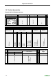
Further technical instructions 5.5 Technical data Electrical data Cable feed: Surface cable routing or flush-type cable routing Mains connection cross-section: Minimum cross-section (depending on the cable and the line length): - 5 x 2.5 mm² (16A nominal current) - 5 x 6.0 mm² (32A nominal current) Mains supply terminals: Connection line: - inflexible (min.-max): 0.2 – 16 mm² - flexible (min.-max): 0.2 – 16 mm² - AWG (min.-max): 24 – 6 - flexible (min.
Further technical instructions Connectors Enable input [X1]: Enable input for external authorization: Connection line: - Cross-section (min.-max): 0.08 – 4 mm² - AWG (min.-max): 28 – 12 Potential-free switch contact output [X2]: Safety extra-low voltage <50VAC 50/60Hz External current limiting to 0.5A required Connection line: - Cross-section (min.-max): 0.08 – 4 mm² - AWG (min.
Further technical instructions 5.
INDEX 6 INDEX A M About this manual ........................................................ 7 Additional optional equipment .................................. 10 Mounting the charging station ................................... 21 Mounting the housing cover ...................................... 40 C O Cable insertion from above - surface cable routing ... 20 Cable insertion from behind - flush-type cable routing ...............................................................................